André Heijkoop’s equatorial platform
I based my
design for my platform mainly on Warren
The
platform I made is for a
Main
dimensions
The main
dimensions (in cm and degrees) for my platform are:
|
Telescope’s Central Gravity |
CG |
50 |
|
Length of Baseboard |
|
70 |
|
Width of platform |
|
70 |
|
Altitude |
|
52º |
|
Rotation angle |
|
11.25º |
Materials
The
materials used:
·
18mm plywood
·
40x90 mm meranti wood
·
30x2 mm aluminum
·
Inline skate wheels ø
72mm, hardness Durometer 82A and ABEC 3 bearings
·
·
Unipolar stepper motor driver CK1404 from
Carl's Electronics Inc.
·
Ø22mm Nylon stepper motor
drive wheel
Sketches of the platform
Main sketch
Dimensions in cm
Click on the picture for a full size version.
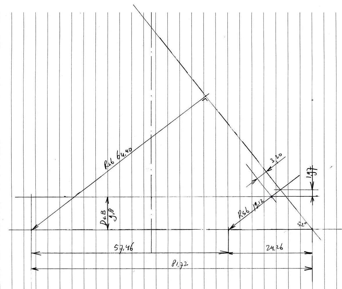
|
Radius North Bearing |
Rnb |
64.4 |
|
Radius South Bearing |
Rsb |
19.12 |
|
Height Baseboard |
D+B |
9.8 |
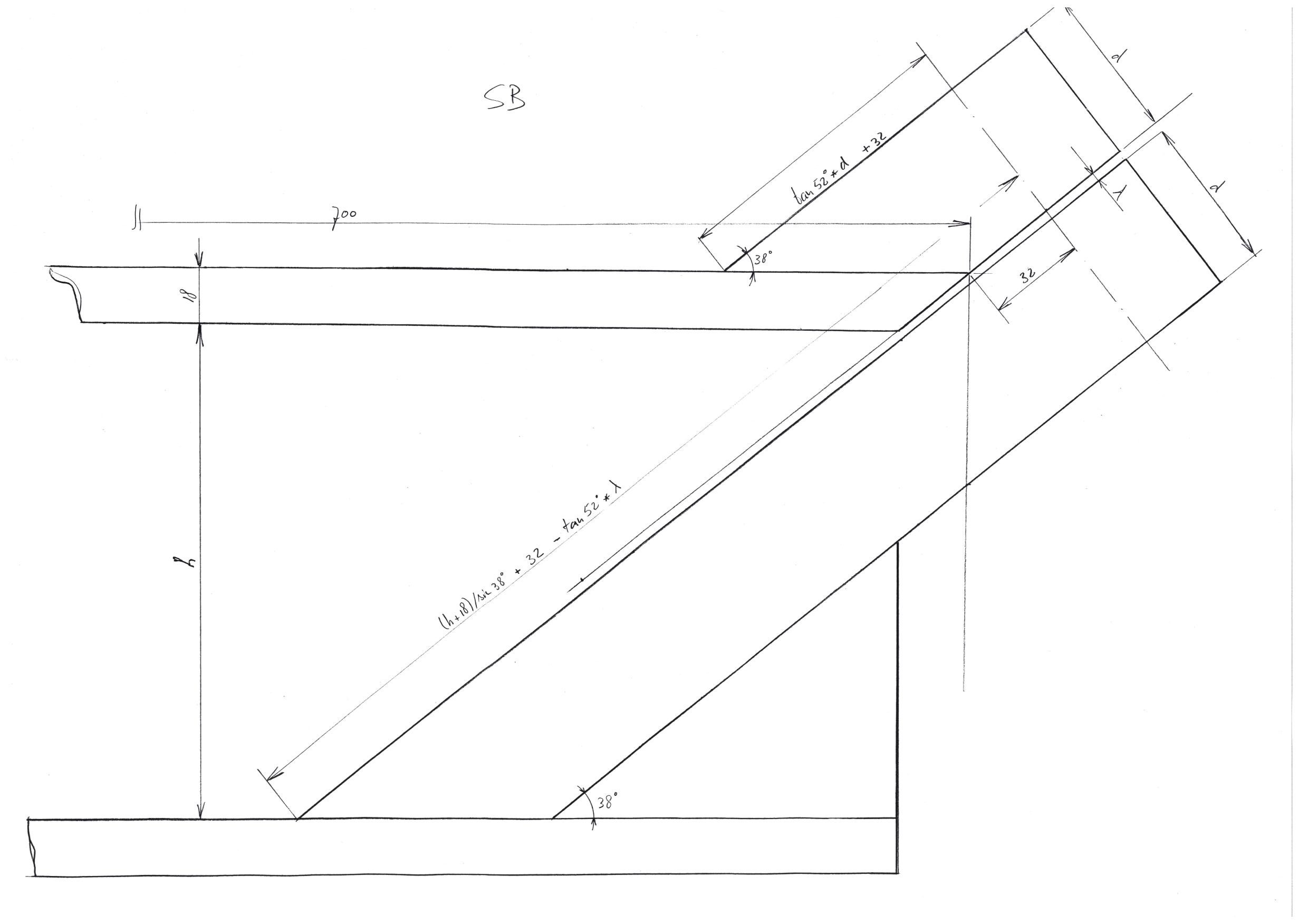
I used
Rnb drawing
To avoid
making mistakes I made very detailed sketches of the North and South bearing
sectors, dimensions in mm.
Click on
the picture for a full size version.

Rsb drawing
Click on
the picture for a full size version.
The
woodwork
The North bearing supports
Constructing the North bearing sector

To make a
good radius on the North bearing sector I made a simple wooden tool, I attached
it with 2 bolts on the ground plate of the router. I made 2 of these sectors
and glued them together to get a sector of 36mm thickness.
Assembly of the North sector
For a
perfect bearing surface I used 30x2mm aluminum.
Assembly of the South sector

South
bearing

I also used
an inline skate wheel for the South bearing.
The
direct drive
The Hurst

I attached
an ø22mm nylon wheel on the Hurst AS3004 stepper motor axis.
The nylon
wheel drives an inline skate wheel at the north sector; the inline skate wheel
drives the platform. With this set up the stepper motor makes an approximately
19 steps per second.
I attached
a spring to get a quick release of the drive wheel during Polar alignment. The
spring is also useful for a fast rewind.
The
inline skate wheel drive

Note:
The little
black box I replaced with a bigger blue box with all the electronics in it.
Electronics
Blue
box
The
electronics to drive the
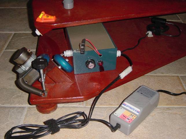
On the
foreground you see the Optimate III to charge the 12V
5Ah battery.
10
revolutions linear pot with digital readout
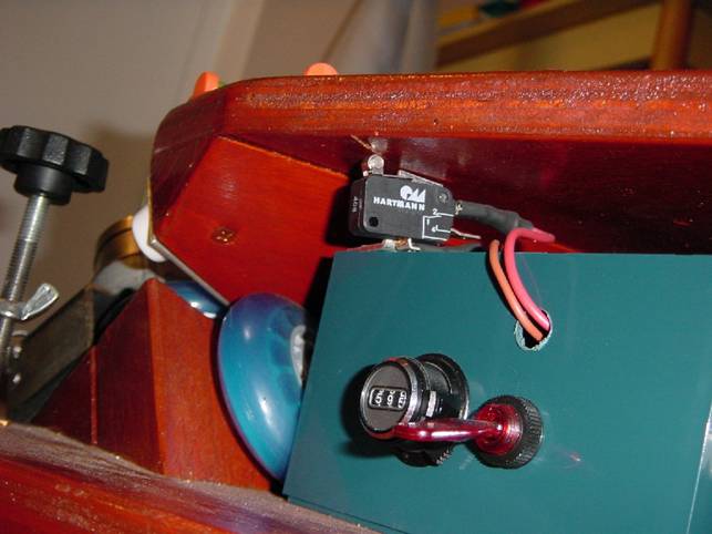
On top of
the blue box you can see the end switch, which cuts of the power when the
platform is at its end of his travel.
On the front
plate of the blue box is a 10 revolutions linear pot with digital readout
mounted, next to the linear pot you see the main on/off switch.
Inside
the blue box
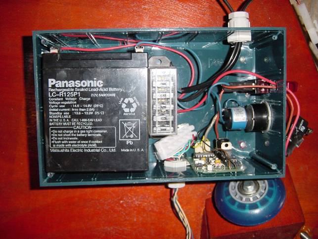
Inside the
blue box you see;
·
on the left the 12V 5Ah
gel battery,
·
in the mid a fuse box,
·
on the right the 10
revolutions linear pot,
·
above the linear pot
the main switch,
·
at the bottom the unipolar stepper motor driver CK1404,
Notes:
1) I replaced the standard logarithmic1M
pot of the CK1404 kit with a 47K resistor and a 100K linear pot.
With the logarithmic 1M pot it is very difficult to get the speed right. The
47K resistor gives the hurst motor a basic speed
which I can easily fine tune with the 10 revolutions 100K linear pot.
2) As you can see in the pictures I
mounted all the electronics in one blue box, pros and cons:
a) Pros
No loose controller boxes on long cables.
b) Cons
Sometimes I have to get out of my observing chair to make small adjustments to
the speed.

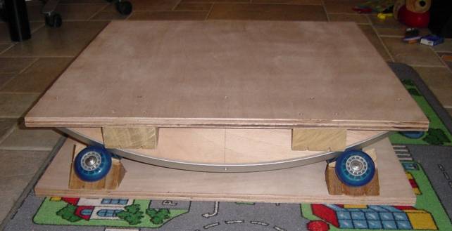
My pride and joy (finished)
The
equatorial platform completed
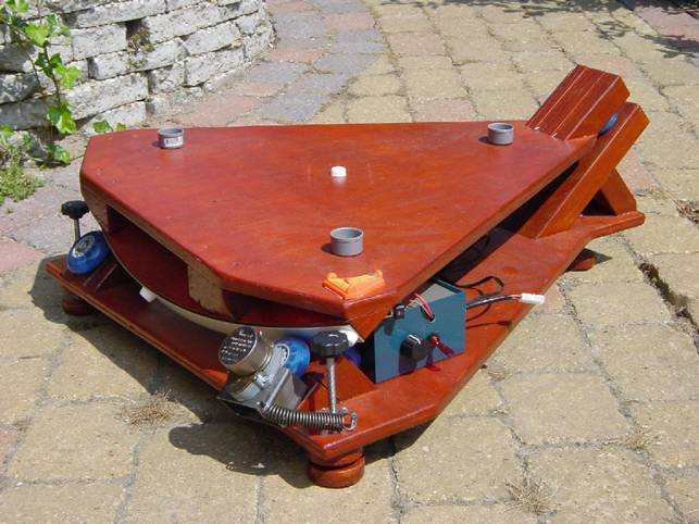
The
complete setup

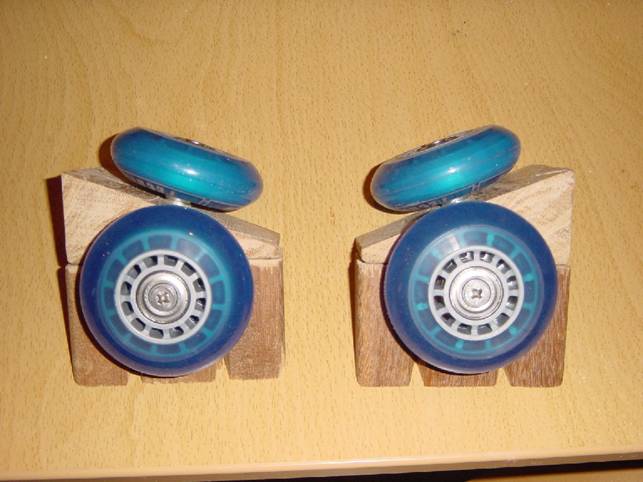
Handle
bars and wheels
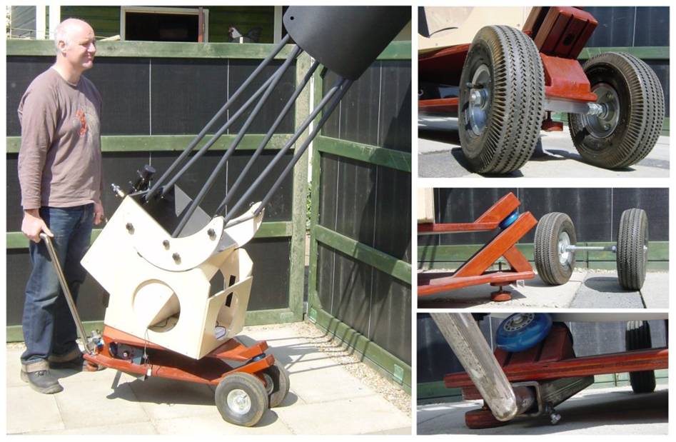
Above you
see the pictures of my homemade handle bars and wheels for my equatorial
platform.
I leave the handle bars almost always attached to the equatorial platform; they
are on the north side of the platform so in the field hardly ever in the way.
The wheels are attached in no time. I just lift the south side of the platform
and roll them underneath. I let the aluminium U-profile underneath the platform
rest on the threaded rod between the wheels, gravity does the rest.
Polar
alignment
I made in
Visio an instruction for an easy polar alignment. This instruction works for a Telrad or RACI finder. Just watch Polaris shift in your
finder and turn or lift your platform according the pictogram.

Credits
·
·
The eqplatforms
group http://groups.yahoo.com/group/eqplatforms/ for the advice and taking away my
doubts.
·
Warren
·
John Reagen for his axial south bearing conversion of Warren
http://www.geocities.com/reaganjj/stepperdetails.html
· Leo van den Heuvel
for soldering the stepper motor driver kit.
·
And all others who
contributed.
Thanks for
reading,
André
Heijkoop
Strijen
Netherlands
51º
04º
http://astrosurf.com/aheijkoop/
![]()