EXview 2005XAL camera modification
|
EXview 2005XAL camera modification |
|
|
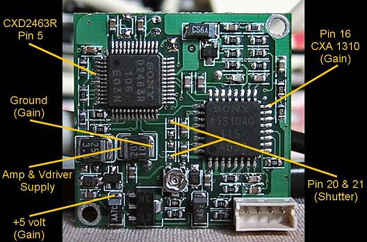
Above, the detailed view of the "battled field" under the printed circuit board of the video camera .. 1) First of all, you have to unsolder the pin 5 of the CXD2463R. This pin is used to power this integrated circuit (+15v)... This will prevent the CCD sensor from emptying from its photons packet :o))) I advise you to use the end of a very thin needle, in order to unsolder and lift pin 5 up. You have to use pin 4 to make a lever arm VERY CAREFULLY, and briefly apply your soldering iron on pin 5... By applying your soldering iron on pin 5, you should feel it moving; heat it with your soldering iron then lift it up carefully with your needle ... Lift pin 5 up as high as the upper side of the IC but not higher or it will break !!! If you managed to do this the most difficult part is done :o))))) 2) You have to do the same operation with the pin 16 of CXA1310. It will allow you to modify the gain of the video camera manually... |
|
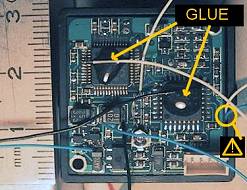
3) On each of these 2 lifted pins, you have to solder a small and very thin wrapped and tined wire. Check your solders and use a 2 component epoxy glue as shown on the picture. The small yellow circle represents a hole you will have to make by filling the shell of the video camera. It will be used by 2 wires coming from the front side of the video camera... |
|
4) As shown on the picture (top of this page) you have to solder the 4 last wires : - the one which collects the +15v (Amp & Vdriver Supply). It will be usefull to power the pin 5 of the CXD2463R and pin 9 of the CCD with relays... - the one which collects the ground for the manual gain. - the one which collects the +5v for the manual gain. - finally the wire which will stop the Shutter. It connects to Pin 20 & 21 of CXD2463R through the two small solder plots top and bottom of the 4 plots serie. In that case a bridge between these two solder plots will be done... Pay attention to check for shortcuts.. between this wire and other solder plots or components Pay also attention to this fact : Contrary to Jon Grove's web site explanations, this wire DOESN'T HAVE TO BE DIRECTLY CONNECTED to the +5v of the PCB in this version, because of the electronic management of the shutter with Steve Chambers' shematics :o). |
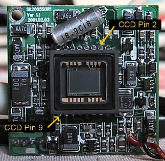
Above, the front side of the video camera with sensor of CCD EXview :o) |
|
The pins of the CCD don't go through the PCB, contrary to 1004XA modification. So you need to lift a pin up and solder two wires from that side of the PCB... 5) As shown above, unsolder and lift the pin 9 of the CCD up, use pin 10 aside with the lever arm... This operation will allow you to reduce the CCD power during the exposure. It will stop the amp. of the CCD to generate luminosity on the left corner of pictures... As before, do this slowly and check that there are no solder bridges connecting pins aside... 6) Now solder a wrapping wire at pin 2 (don't lift it up), check that there are no solder bridges connecting pins aside. Using a diode from Pin 2, grounded by a relay, will allow us to choose the moment to power it on & off to get the 2nd "trame" in high res. mode... |
|
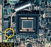
7) You have also to solder a tined wire (with a little solder on it, befor final soldering) on pin 9. Then, like on the other side, check that these two wires are well soldered and glue them using a 2 component epoxy glue as indicated here on the left :o) I have decided to unsolder the 2 unused wires and the small unused microphone (It can be annoying when mounting the video camera in its shell... ). |
|
The internal modification of the video camera is finished :o))) You can integrate the PCB in its original shell and close the back side. Take care to use the hole you made (on the right side of the shell) and make some wires go through it. The rest of the wires can go out under the 4 pins connector at the rigth bottom of the video camera. PAY ATTENTION to identify the wires correctly before closing the shell !!! If you want to test your video camera in 'normal mode' before the next step you have to connect the wire associated to pin 5 of CXD2463R and the wire associated to the pin 9 of the CCD, to Amp & Vdriver Supply's wire. Now connect wire associated to pin 16 of CXA1310 to the ground. Turn on the video camera and you should have a "normal" picture on your TV, or computer using USB Live :o) If it doesn't work, double check your wires/solders and check for unwilling bridges/shortcuts..... You can also test for a long exposure by inserting a on/off switch between the wire associated to pin 5 CXD2463R and wire associated to Amp & Vdriver Supply !!! By turning off briefly the switch, you will have a black picture. As the contact comes back you should see a white flash which is an over exposed picture contained in the continuous stream of the screen picture :))) |
|
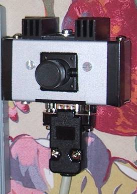
Let's move on to the "Box part" of this video camera project... 8) You are free to choose your box !!! I used a small(10cm x 4cm x 3cm) aluminium box (to prevent heat problem). I managed to put the video camera, a 9 pin connector (same as a serial port), the small plate with the potentiometer used for the manual gain setting (accessible through a small hole in the box) and three small relays which have to be near the modification to be efficient :o) I emptyed a square zone on the front side of the box to fit the bigger dimensions of the front side of the camera. I drilled two holes in the box and two holes in an iron piece, I have put the iron piece behind the PCB, and screwed all this to fix them together :o) To fix a radiator I also drilled a hole on the top side of the box (because of the heat produced by the original shell of the video camera)... (Because of all this aluminium, the camera stays now at a low temperature :o) ) You have to make holes to fix the 9 pins serial connector. I chose to fix it at the bottom of the box... After this, you are ready to insert the plate of manual gain setting and small relays wiring :o) |
 (Steve Chambers' diagram) |
Here comes the "control of manual gain setting" part of our project... 9) You have to solder on a small "electonic tests board" the 10Ko potentiometer, the 0.1 UF condensator and the three wires : Ground, +5volts, pin 16 of CXA1310 coming from the camera, as shown on the left picture :o) You can cut this plate, as I did, in order to fix all the parts with a small screw. A hole will be used for the screw and the other one will be used to access the potentiometer (all this near the 9 pins connector)... I inserted two nuts in order to separate the plate from the box :o) |
Clik here or click on the picture to enlarge (Steve Chambers' diagram) |
AT LAST, the "settings of control relays" part 10) Now we have to wire relays as shown on the left side picture. Take care to understand the function of each pin of your relays. (common, on, and off pin) I connected +12v and "Control" to the 9 pins connector, I checked each pin and its function... The condensator, the resistor and the small 3 diodes (protection of coils) are soldered directly on the pins of the relays. The diode used for pin 2 of the CDD is connected to the ground pin of the 9 pin connector :o) Take care to shortcuts with the metallic box. Each relay has been isolated with rubber and inserted into the box near the video camera. All this is fixed with rubber :o> |
|
Regarding the main power supply of the video camera (+12v), video signal and ground, I used the original connector of the video camera, but I cut the cable about 5cm from this connector. Then I soldered the wires directly to the 9 pins connector :o) For your information the small connector at the right bottom of the video camera is from left to right : +12v (red wire), ground (black wire), video (yellow wire) and audio (white wire, not used here). For the 9 pins connector I only used 7 pins : - +12v - ground - video - V3 control - Vh control - Amp control - Shutter coming from inside the video camera... Here we are !!! :o)))))) You can now screw the box, you now have a modified EXview Video Camera ready for long exposure, a bit "refreshed" and ready to be plugged into the electronic control box... |
| Back to the 2005XA Menu | USB Live Modif Page |