
New features
of version 4.13
(March
21, 2004)
Update V 4.13
Support of RAW format for the digital SLR Nikon D70.
NEW COMMAND
ASINH [ ALPHA ] [ INTENSITY
]
This command is for processing red, green
an bleue (RGB) composites from three-band astronomical images. ASINH stretch
the image to sho faint objects, while simultaneously, preserve the structure
of bright objects of the field. The color contrast is boosted by the application
a non-linear stretch : the Arc Sinus Hyperbolic function. This method permit
to reveal an enoumous amount of information: index color of stars, faint nebulae,
galaxies having a distinctive colors (see for example, the Hubble Deep-Space
images of the HST, many time processed with a function very similar to ASINH.
The arcsinh is a new manner
of defining the magnitudes scale, see R. Lupton, Astronomical
Journal, 118, 1406-1410. This scale magnitudes has properties very interesting
when one applies to color images colors because it boost the colors index of the objects (see R. Lupton & all, PASP, 116,133-137). The colors
contrast
is very strongly accentuated whereas the noise increase is
contained.
The parameter [ alpha ] permit to adjust the non-linearity factor. A null value corresponds to a standard linear scale. The characteristic values go from 0.001 to 0.1. The parameter [ intensity ] adjust the intensity of the final image. The characteristic value for this parameter goes from 1 to 50 (carry out tests and exploit the visualization thresholds).
Here some application examples.
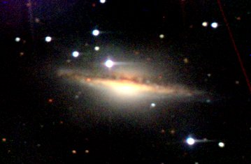
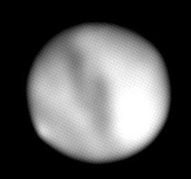
Look the color image of galaxy NGC 1055. It was produced starting from three distinct CCD frames taken through filters red, green and blue (photometric RVB system) with the telescope of 60 centimeter telescope of Pic du Midi. Visualization is traditional, linear in intensities. The nuclear region appears of a saturated.
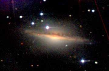
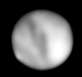
Below the same object, but after having used command ASINH 0.01 20. The core is less saturated and the extensions of the galaxies become visible. To obtain this effect you must initially display the 48-bits image colors with screen, then applied ASINH. For example:
TR N1055_R N1055_G N1055_B (or use command (L)RGB Visualization menu)
ASINH 0.01 20
You can also use the dialog box Colors Stretching... from the Visu menu.
Now, the result of command ASINH 0.05 20. At present, at the same time the core and the extensions are visible simultaneously whereas the noise is only moderately accentuated. Note the trail of satellite, presents in the red image, not easily perceptible with a linear, but clearly visible in the image processed with the command ASINH(boost of color contrast).
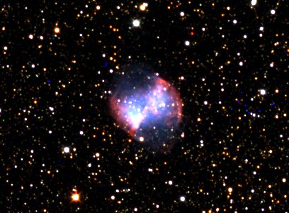
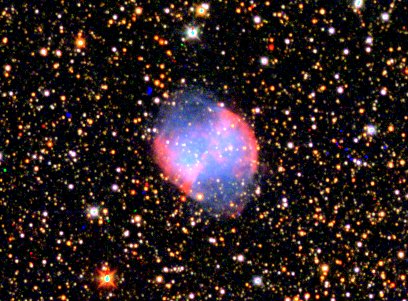
The example below shows an image RVB composition taken with a Takahashi Epsilon 160 (M27). On the left, linear visualization, on the right, arscinh visualization.
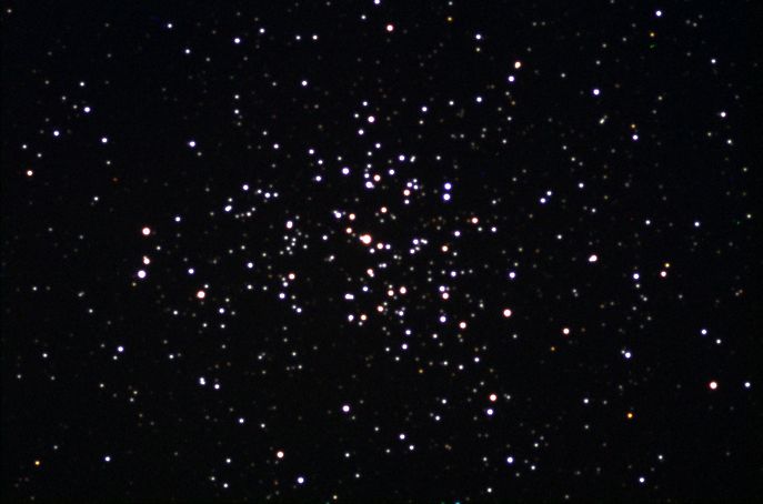
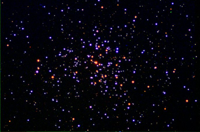
Successively a composite image of the cluster M37 with linear visualization and after ASINH command (CCD Audine camera and refractor Takahashi FS-106). Now, stars show a variety of red and bleus tints. Two star populations are clearly revealed.
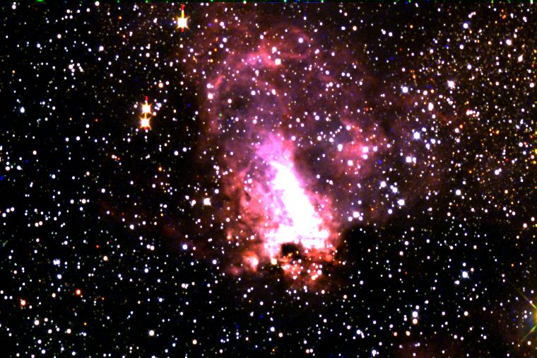
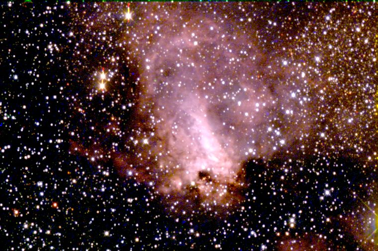
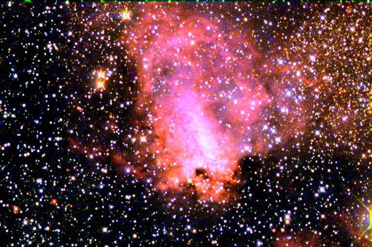
The last example shows the application of the arcsinh technique applied to M17 (image 60-cm telescope of the Pic du Midi). From top to bottom, linear display, logarithmic display (command Logarithm Visualization menu), arcsinh display.
Update V 4.12
NEW COMMANDS
ADD_MAX [NAME]
Suppose
the intensity I1(x,y) of a pixel in the image I1 at coordinates (x,y) and
the intensity I2(x,y) of a pixel in the image I2 at the same coordinates
(x,y). ADD_MAX produce
a new image, I, where the intensity of pixel (x,y) is:
I(x,y)=I1(x,y) if I2 <= I1
I(x,y)=I2(x,y)
if I2 > I1
In other word, a pixel of image I1 is replaced by a pixel of image I2 if the local intensity of I2 is superior to I1.
The usage of ADD_MAX is simple:
LOAD I1 (load
in-memory the I1 image)
ADD_MAX I2
(compute substitution)
SAVE
I (save
the result)
ADD_MAX is compatible with 16-bits format (gray level images) and 48-bits format (true-color images).
ADD_MAX2 [NAME] [NUMBER]
Function
very similar to ADD_MAX
but process many images simultaneously. For example for stack images I1, I2,
I3, I4, I5, enter the command:
ADD_MAX2 I 5
This function is very efficient for construct long exposure star-trails images. About this method read the excellent paper of Peter Michaud (Gemini observatory) in the Marsh 2004 issue of Sky and Telescope.Example, consider 16 images of the one-meter telescope of Pic du Midi observatory taken by François Colas during the 2003 AUDE star-party (images PIC1, PIC2, ..., PIC16). Here the first three frames of the sequence:


OK, now we add the images:
ADD2 PIC 15
Hum, the result is not very good. The star-trails contrast is very modest because the observatory is lightened by the full-moon.
Now, apply the ADD_MAX2
command:
ADD_MAX2 PIC 16.
The star-trails are well visible:

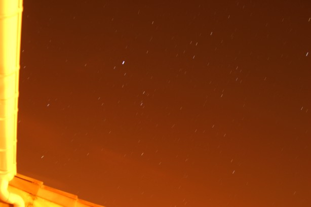
The technique is applicable under very polluted sky. Here the simple arithmetic stack of 9 frames (10-seconds exposures with a DSLR Canon 10D from my city-observatory, in Castanet-Tolosan, near Toulouse, France):
The naked eye limit magnitude is only 2 for the date of this observation! Consequently, the Lyrae constellation is very faintly visible.
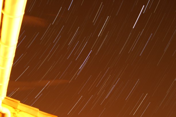
Now the ADD_MAX2 command result:
Here a 20-minutes exposures for similar conditions (note cloud transit - the bright star is Arcturus):
L_GAUSS [SIGMA]
Convolution
of a vector image by a gaussian function. The sigma of the gauss function is
given in parameter. For a typical application click
here.
LOADTIFF [NAME]
Load
and display a TIFF image.
JPG2PIC [IN] [OUT] [NUMBER]
Convert
a sequence of JPEG file to PIC or FITS sequence (the final format is dependant
of the choice in the setup dialog box of File menu).
Consider the
input sequence IM1.JPG, IM2.JPG and IM3.JPG. To convert to image R1.PIC, R2.PIC
and R3.PIC (or R1.FIT, R2.FIT and R3.FIT), enter the command:
JPG2PIC IM R 3
TIFF2PIC [IN] [OUT] [NUMBER]
Convert
a sequence of TIFF file to PIC or FITS sequence.
PIC2DATA2
[DATA FILE NAME] [FIRST VALUE] [STEP]
Convert
a vector image to a data ASCII file (two-column). The first value of the first
column is given en the step between two successive value. This function permit
to export wavelength calibrated spectra for example.
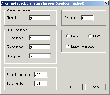
Improved alignment et stacking procedure for planetary images
More precise function for automatic planetary image processing (concern also lunar images). See the command COMPUTE_TRICHRO1. This command can now be called from a dialog box (menu Processing and item Align & Stack (1)...). The possibility of process black and white sequences is added.
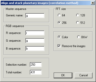
Before invoque this dialog box draw a rectangle around the planet disk. The size of this rectangle define the area where the best crisped image is computed (BESTOF procedure):
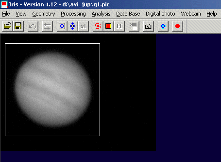
Remember to select a FFT size superior to the planet diameter. For example, if the disk diameter is of 182 pixels, select a FFT sub-image of 256 pixels (but not 128 or 512 pixels). You can also erase the intermediate image at the end of the processing, and if not, it is possible to recombine later the individual true-colors produced (the generic name of this images is @ - ranged from the better to the lower resolution). To see the first image of the sequence (the best resolved), enter:
LOAD @1
For example, stack the 100 first better images of the computer sequence:
ADD_NORM @ 100
Tips: for remove the intermediate images, enter REMOVE@
A dialog box equivalent to the console command COMPUTE_TRICHRO2 is also added (use of a circle method for the determination of the planet position):
Other feature: the commands ADD_NORM,
WINDOW3 and WINDOW3
support now the 48-bits internal format (true-colors image).
Update V 4.11 (February2, 2004): Fixed pattern noise removal and Fuji FinePix S2 Pro support
Fixed pattern noise removal
IRIS V4.11 compute a FFT (Fast Fourier Transform ) to evaluate fixed pattern noise of an image. Next, the fixed pattern noise is corrected through boxcar filtering. Finally, the reverse FFT display the corrected image.The command for direct FFT is FFTD,
the commande for inverse FFT is FFTI,
and the boxcar filter is FFILL.
Here an application example.
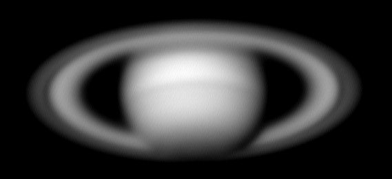
Consider this Saturn image from a webcam (image Sylvain
Weiller). Periodic parasitic electrical noise is clearly visible:

First of all the direct FFT:
FFTD X Y
The two parameters are the file names for the modulus and argument of the FFT (the result of this FFT is in polar coordinate representation). The modulus is displayed on the screen.
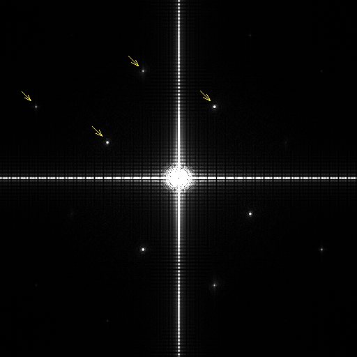
The two-dimensional FFT can provide information in the frequency domain in both the horizontal and vertical directions and, in particular, will indicate any modulation of a parasitic signal. The arrow indicate the peak frequency of the fixed parttern noise: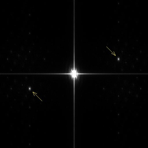
Now, mask the noise peak by the use of FFILL command. FFILL is very similar to FILL2 command, but fill with a given value two area symmetric with regard to the x-axis and y-axis. Remove the principal parasitic peak. Drag a small rectangle around one of the peak...

.. . then: FFILL 0
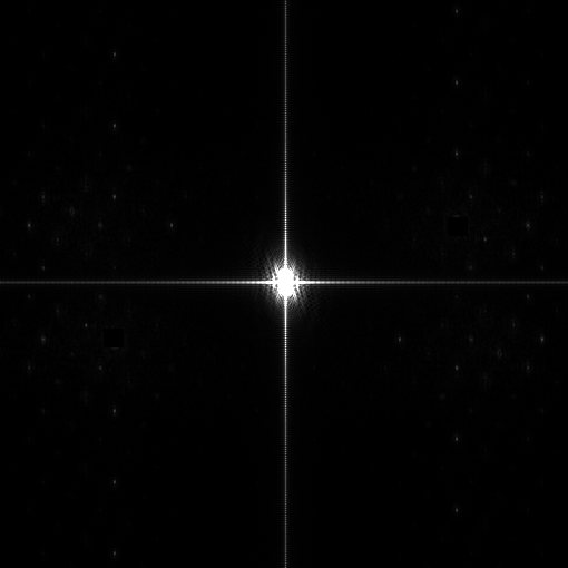
Save the modified module component of the FFT (important):
SAVE X
Now compute the reverse FFT:
FFTI X Y
The result is now a very clean image:
Another example, a webcam image of Mars planet (document: Pierre Thierry):
Many parasitic frequency are visible:
After removal:
And the rectified image:
Other FFT in V4.11:
FPOLREC [MODULUS] [ARGUMENT]
Transform the frequency domain images from polar to rectangular.
FRECPOL [REAL PART] [IMAGINARY PART]
Transform
the frequency domain images from rectangular to polar.
FCORREL [IMAGE #1] [IMAGE #1] [COEF]
Compute
the cross-correlation of images #1 and #2. The [coef] coefficient is an intensity
scale factor for the result. Example:
FCORREL MARS1 MARS2 1
Support of the raw format of digital SLR FUJIFILM FinePix S2 Pro
The extension of Fuji's file is .RAF. The peculiar CCD used by this DSLR is a complication for extraction of a comprehensive image (45 deg. organisation of raw and column), usable for post-processing. Here a characteristic CFA image of the Fuji FinePix S2 Pro:
After post-processing and extraction of RGB component (only after), rectify the geometrical aspect of the image with this set of commands:
ROT 1792 1792 -45
WINDOW 277
776 3307 2810
If the RAW
image is directly loaded from the file menu the geometric corrections are automatic:
New of V4.10 (January 17, 2004)
Support of RAW format of the DSLR Pentax *ist D (.PEF extension)
New functions for the Decode RAW files (Digital photo menu) dialog box: In addition to conversion of RAW files into CFA files, it is now to directly obtain a colors or Black & White sequence of images (B&W = sum of red, bleue and red planes):
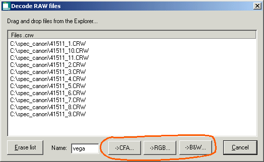
Addition of a dialog box for convert a sequence of CFA to 48-bits colors sequence (Digital photo menu).
Commands ADD2, SOUST2,
MULT2, DIV2 and OFFSET2 (and their equivalent of
the Processing menu) support the 48-bits colors internal format.. Command STAT returns now
information on the three colors planes of the in-memory 48-bits images.
For
a tutorial about DSRL RAW processing click
here.
Support of video cameras
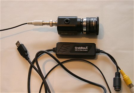
The appearance of small video cameras for survey purpose, very sensitive and relatively inexpensive, offer interesting possibilities: high-resolution imagery by image selection, pointing, detection of fugitive phenomena (meteors), active optics.... One can quote in particular models range Watec (Wat-120N for example). Click here for some information on the subject and comparative test.
If these cameras are associates with a video encoder connects to USB port (USB2 necessary), their use is very similar to a webcam. Iris 4.10 was adjusted in particular and tested for the digitizer GrabBeeX (USB2 version), a compact and autonomous interface (powered by the USB port). The video stream can be displayed through the Preview command of the Webcam menu, but all the other acquisition modes are possible, in particular the image by image mode.
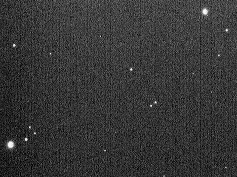
Photography below shows an economic camera Watec LCL-903K equipped with a CCD sensor Sony 1/4 inch (weight of 130 g) and the encoder GrabBeeX USB2.
The image below of the central field of M42 was obtained with this equipment and a Takahashi FSQ-106 refractor. It is the stack of 10 images at the maximum gain of the camera from the Images acquisition... command of Webcam menu.
RAW mode of the webcams (Philips ToUcam Pro, Philips Vesta Pro)
The internal program iof some webcams, stored in a EEPROM, can be modified so that video stream, instead of delivering RGB images, produces CFA images. After this change, the images show a completely traditional Bayer matrix, and Iris tools for RAW image processing RAW can be applied.
An excellent page of Etienne Bonduelle describes in detail how " to transform " your webcam for the RAW mode. The process reversible and it is software based. See: http://www.astrosurf.com/astrobond/ebrawf.htm
Essentially, version 4.10 corrects a problem at the time of the capture for B&W and facilite RAW extraction from the video flow. The notes below describe briefly how to exploit webcam RAW format with Iris.
1. Simple capture of a RAW image
In this version it is first of all desirable to configure Iris for the use of proprietary PIC file formal than FITS. Two interests: a processing slightly faster, especially, the transparent processing of true colors (48-bits storage). For that, open the Setup... dialog box from the File menu and select PIC option:
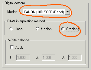
It is then necessary to indicate to Iris the order of red, green and blue pixels of the CFA matrix array. This information is essential to restore real colors after decoding the CFA image. For that, to open the Camera settings dialog box (click on the camera icon of the tool bar). There is no adjustment specific for the webcam, it is necessary to choose among those offered for various cameras numerical. Generally good decoding for ToUcam Pro is obtained by selecting the option Canon (10D/300D/Rebel), but it happens that another choice should be made (with my own ToUcam, the Nikon D1 is the good choice!). By making tests one is quickly fixed. In this same dialog boxes, choose the method of extraction method for demozaicing the CFA array. The linear interpolation is fast and often satisfactory for the deep-sky imagery, but for an optimal result, giving the maximum resolution, the gradient is to be chosen.
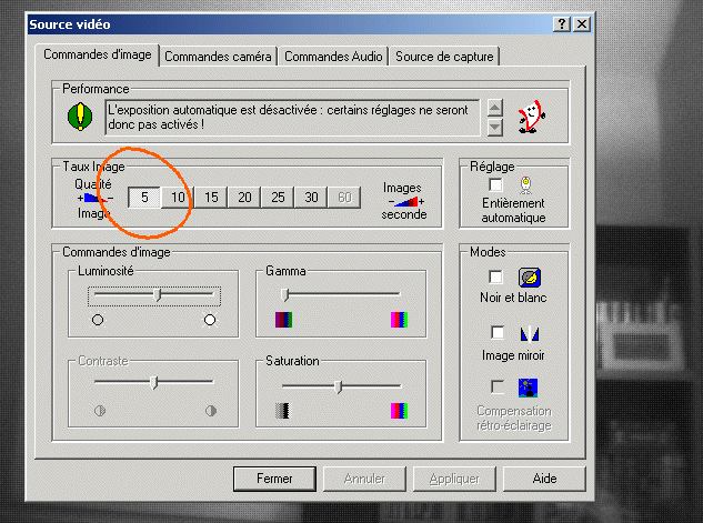
After connected the webcam, from Webcam menu, run Preview command. A gray image, a little granulous (Bayer matrix is evident), must appear. Run Video properties... command of from Webcam menu to ensure that the acquisition frequency is done well at the frequency of 5 images per seconds (a higher frequency scrambles CFA structure because of the insufficient bandwidth of electronics of the camera).
Close this dialog box.
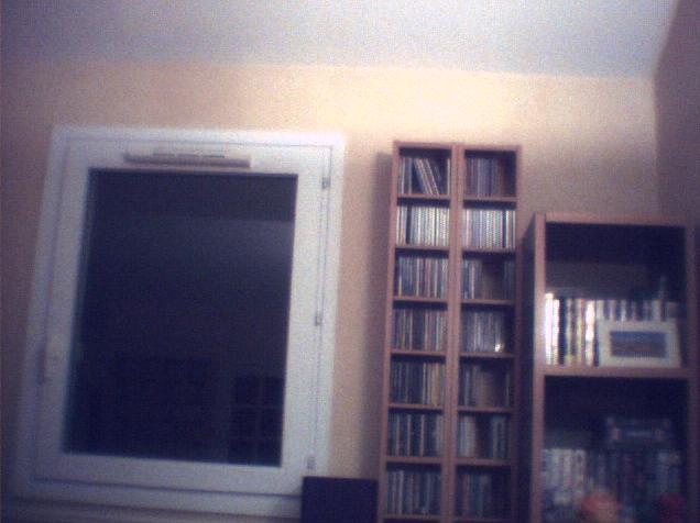
To acquire a simple image run the One shot command of the Webcam menu. A monochrome grayscale CFA image appears on the screen (16-bit coding). To transform this document into a 48-bits true colors image, run the command Convert a CFA image from the Digital photo. Here the result:
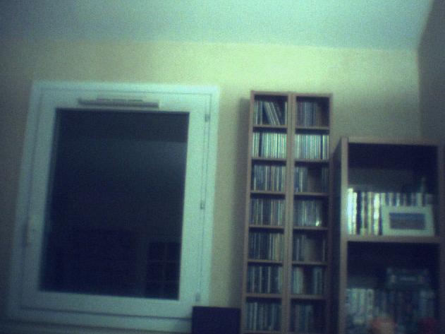
One can simply adjust the white balance by using WHITE command (from the console). First, define a small rectangle in the image delimiting a part considered white (here, the edge of the window):
This image is now a 48-bits true colors document. You can save it in a single file (PIC, JPEG, ..., file format.), and many processing can be applied directly without having to pass by the separate colors planes (for all the details, click here).
2. Capture of a sequence of RAW image
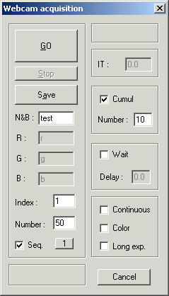
To open limps it of dialogue Acquisition Webcam... of small Webcam. To fill like below:
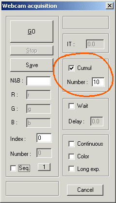
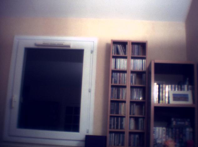
Click the GO button. Iris carries out the acquisition of 10 CFA images CFA, added in real time, then displays the result. If need be, adjust the visualization thresholds if the image appears too white. You can immediately see the colors aspect of the image: run the Convert a CFA image from Digital photo menu. The SNR ratio is appreciably well improved:
You can merge stack of individual images and produce on the hard disk a sequence of the added images. Here how to fill the box acquisition dialog box (an example):
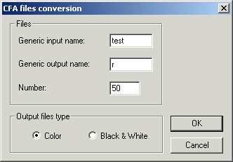
It is easy to transform the 50 CFA images acquired into color images (or grayscale images): use the batch dialog box Sequence CFA conversion...:
You can add these 50 images since a console command: ADD2 R 50, or while running the Add a sequence... command for the Processing menu.
3. Extraction of image CFA starting from a AVI film
An AVI film is obtained in a usual way, even when the camera is modified. CFA images sequence is extract from the AVI by the use of dialog AVI conversion... from the File menu. Remember to select Black and White option:
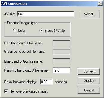
|
|
