New features
of version 4.22
(click here for download the version)
Support of the Digital SLR Pentax *ist DS
(select the Pentax *ist DS option from the camera settings dialog box) and
Olympus E-300 (select the Olympus option from the camera settings dialog box).
COM3 and COM4 are added for the LX200 protocol.
Support of the Digital SLR Konica-Minolta 7D RAW format
(select the Minolta option from the camera settings dialog box).
NEW COMMANDS
CIRCLE2 [THRESHOLD]
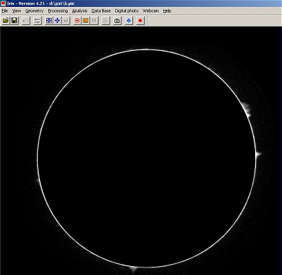
Compute the center and the radius of a circular object (planet, sun, moon, ...). The radius value is computed for a given intensity threshold in the image. CIRCLE2 differ from CIRCLE command by the method used for identify the objet. CIRCLE use a dragged rectangular area, CIRCLE2 define the rectangle from two clicked points (more useful for large images).
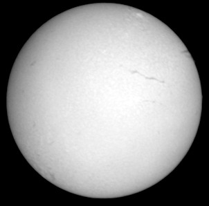
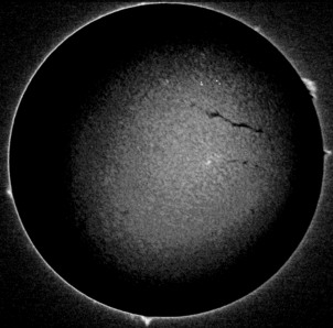
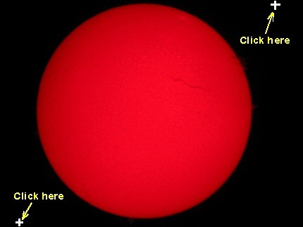
Example (on a Coronado PST Ha image of the Sun taken by Franck Vaissiére):
Then, enter the command : CIRCLE2 50
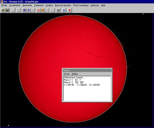
IRIS return this coordinates for the disk center
: X=381.54 and Y=306.63. The radius is about of 284 pixels for the outer part
of the disk.
Note 1: The CIRCLE and CIRCLE2 commands are true-colors compatibles (48-bits images - but remember,
use the proprietary PIC format for exploit these possibilities).
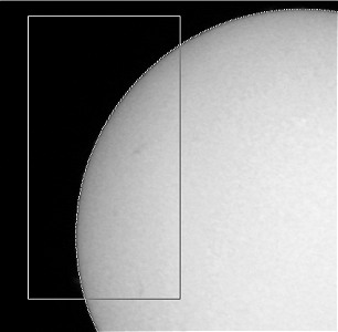
Note 2: The CIRCLE and CIRCLE2 commands can compute the disk parameters from an arc. It is useful if only a part of the objet is visible, but the precision is lower comparatively to a full disk analysis. Example:
Note 3: From the observed radius R the equivalent focal length F of the system can be easily to estimated:
F = 2 x p x R / tan(alpha)
with p the physical size of detector pixels (more precisely, the pixel sampling), R the observed radius of the object in pixels and alpha the apparent diameter of the object.
For example, for the present images the digital camera is a Canon A40. For this model p=3.3 microns=0.0033 mm. The measured radius of an unscaled image is R=569 pixels. For the date, the apparent diameter of the Sun is alpha=0.542°. Finally, the focal length of the optical system (coronado PST + eyepiece + APN) is:
F = 2 x 0.0033 x 569 / tan(0.542) = 397.0 mm
DISK1 [X] [Y] [R]
DISK1 draw a dark disk on the in-memory image. This function simulate for example a coronographic effect on Sun images. The parameters are the coordinates of the disk center and the radius.
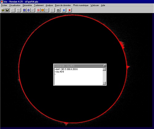
For example (see also the CIRCLE2 command for informations about the image):
DISK1 381.5 306.6 283.6
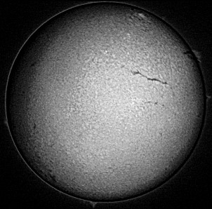
DISK2 [X] [Y] [R]
This function is the opposite of the DISK1 function: The outer part of the defined disk is masked.
The simultaneous use of DISK1 and DISK2 is a solution for enhance the aspects of prominance on the Ha image relatively to the disk.
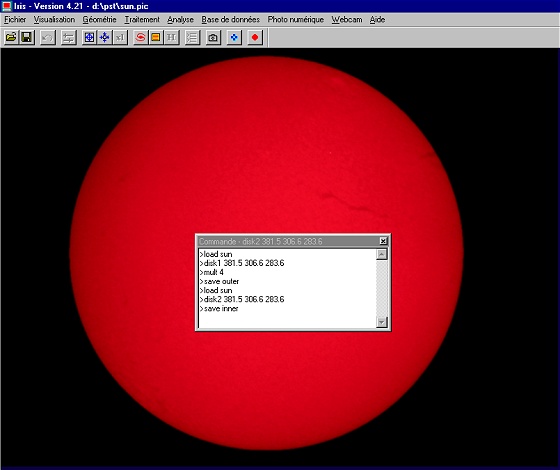
Example: Apply the DISK1 command, multiply the result by 4 (try some value) and save the result:(give the name OUTER for example):
DISK1 381.5 306.6 283.6
MULT 4
SAVE OUTER
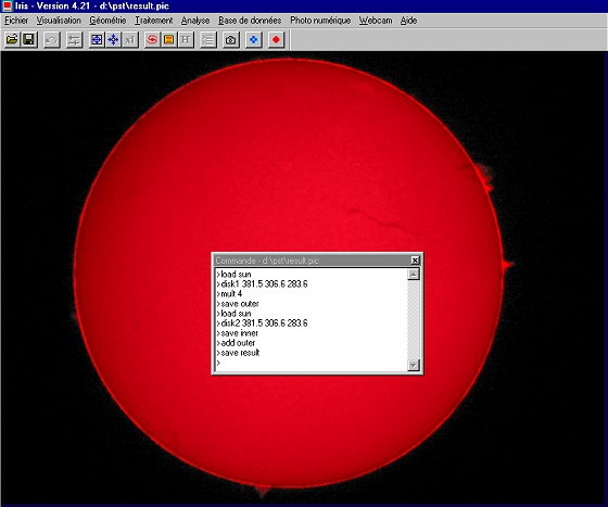
Now, use the DISK2 command for isolate only the sun disk image: DISK2 381.5 306.6 283.6
Finally, add the inner and the outer images:
ADD OUTER
REC2POL [X] [Y] [R] [SCALE (deg./pixel)]
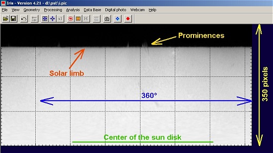
Transform the natural "circular" aspect of the sun chromosphere to a polar representation (an axis is the distance from the center of the disk and an axis represent angular values). (x, y) are the coordinate of the disk center image in pixel. [r] is the max. radius of the polar representation in pixels. The [scale] parameter is the number of degrees by pixel unit in the final image (typical values are from 0.5°/pixel to 0.1°/pixel).
Example.
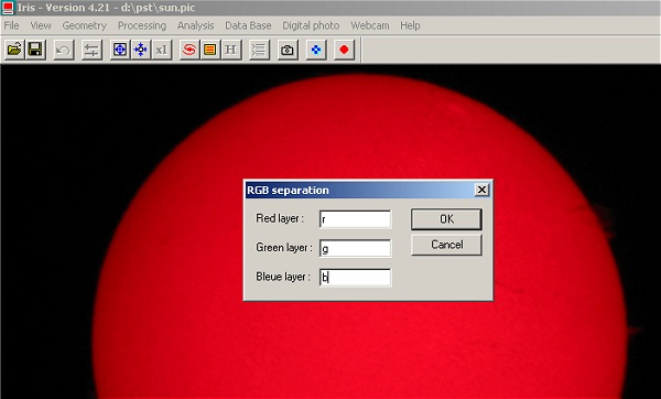
The processed image is taken with a digital camera. Only the red channel contain the major information for Ha wavelength (some time information is also present on the green and bleue channels, but the color balance is very dependant of the dye filter technology used in the digital camera). First, it is truly recommended to isolate the RGB channels from the 48-bits images and use only the red frame for prominence studies. Run the RGB separation dialog box (Digital photo menu) for extract the R layer.
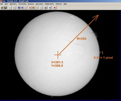
Load the red image: LOAD R
Run the REC2POL command. The parameters are X=381.5, Y=306.6, R=350, SCALE=0.5°/pixel
Note1: For an optimal sampling of the transformed
image, choice a scale factor of 0.1 - 0.2°/pixel.in general.
Note2: The radius of the transformed image include largely the apparent disk
of the observed sun.
Here, the result of: REC2POL 381.5 306.6 350 0.5
For a more classical representation horizontal angle axis), use MIRRORXY command for rotate (or use Flip dialog bow of the Geometry menu). You can also draw a coordinate grid (a tick for each 5° in this example):
The signification of this image:
See also the cartographic possibilities of IRIS (MAP command).
POL2REC [X] [Y] [R] [SCALE (deg./pixel)]
Convert a polar representation of an object to a cartesian representation. The parameters are the same to the POL2REC command.
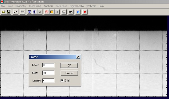
LFILL [X0] [VALUE]
Mask the left part of an image relative to the [x0] coordinate. Iris give the level [value] to the masked area.
RFILL [X0] [VALUE]
Mask the right part of an image relative to the [x0] coordinate.
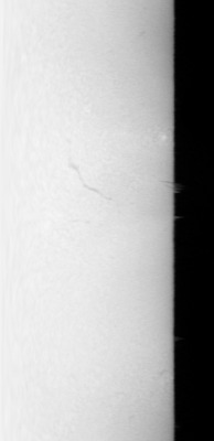
Application: how to make a coronographic effect (artificial solar eclipse) form the rectangular representation of the sun surface ?
First, measure the x-position of the sun limb in the rectangular representation:
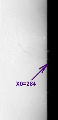
then: LFILL 284 0
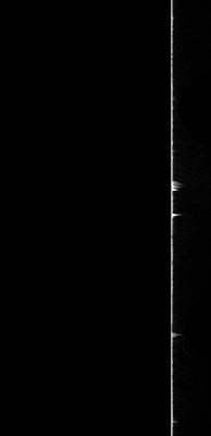
Finally: REC2POL 381.5 306.6 350 0.5
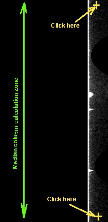
L_EQUAL
For each column of the image, the software substrat
the median value computed between two points selected with the mouse. Example:
remove the parasitic gradient around the sun limb (diffused light by the optics
and atmosphere) for enhance faint prominences.
|
|
|
Run the L_EQUAL command. Select two points along the vertical axis (click with the mouse). |
After the second click, Iris remove the radial gradient around the sun. |
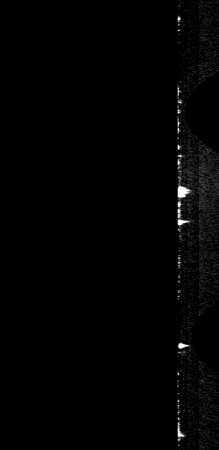
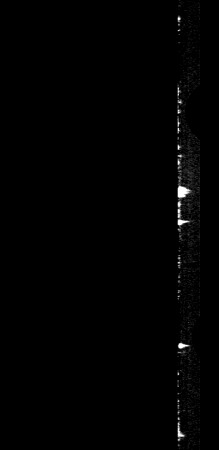
Th aesthetic, the non-significant part at right is masked: RFILL 319 0 |
Execute the REC2POL command and display the result (high contrast visualisation):
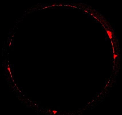
Note1: for a red representation of the prominences
execute for example this sequence: SAVE
R, FILL 0, SAVE G, SAVE B, TR R G B.
Note2: The L_EQUAL can be also used for suppress the limb darkness effect.
EQUAL [X1] [Y1] [X2] [Y2]
Fit a polynomial surface in the area defined by the point (x1, y1)-(x2, y2), subtract this model (only the area is modified) and add the median level.
POL2REC2 [X] [Y] [R] [POS. ANGLE] [SCALE (deg./pixel)]
Very similar to POL2RECbut the added parameter [pos. angle] offer the possibility to adjust the origin of angle in the rectangular representation. You can take into account the apparent orientation of rotation axis of the sun for example. The angular value is given in degrees (the default value of the POL2REC command is [pos. angle] = -180°).
About the CREGISTER command
CREGISTER is the ideal function for registering sun images. The command is now directly compatible with 48-bits images. Usage is simple: give the generic name of the sequence (for example SUN, for SUN1...SUN5), the generic name of the output registered sequence (for example I, for I1...I5), the threshold level (like a CIRCLE command) for detect the limb (for example 30), and the total number of images in sequences (for example 5). For this example the full command is:
CREGISTER SUN I 30 5
For the following example, five Canon A40 images are registered and added. You can note a maximum flux into the R channel (normal for a Ha image), but also some signal in the B channel - and curiously a better contrast (the B-filters transmission + spectral detector sensitivity is near 10% of the R channel near the red hydrogen line). Nothing external processing is applied to this images. The internal firmware processing for this APN is severe for the G and B channel (contour effects - contrast, ...).
|
|
|
R channel |
G channel |
B channel |
QM [NAME1] [NAME2] [TYPE] ( or QMOSA [NAME1] [NAME2] [TYPE] )
Assemble the image [name1] and [name2] in an unique image. QM is optimized for stellar images : the commun point between the two images is a star selected with the mouse (a simple click). QM is very easy to use but the operation is rudimentary: only the relative translation between the images is considered, not the distortion for example. QM is an interactive version of MOSA command. The parameter [type] define the junction zone of the two images. If type=1 the image 1 is on image 2, if type=2 a pixel in the commun zone is the maximum of image 1 and 2, if type=3 a pixel in the commun zone is the minimum of image 1 and 2, if type=4 the commun zone is the mean intensity of image 1 and 2, if type=5 an interpolation is computed between images 1 and 2 for a more natural transition . For the majority of situation the type=5 option is preferred. QM can process black and white images and true colors images. Example, assemble the two images :
The two images. A correct commun star is indicated (bright, unsatured and isolated).
The image after two mouse click and "QuickMosa" operation.
QM2 [NAME1] [NAME2] [TYPE] ( or QMOSA2 [NAME1] [NAME2] [TYPE] )
Same as QM but for non-stellar images. Iris use the intercorellation technique around the clicked zone. Example:
|
|
First image. Click on a contrasted detail. |
Second image. Select the same detail. |
The result after QM2 IM1 IM2 5
Version 4.20 - November 27, 2004
NEW COMMANDS
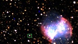
Four new commands are added for a quick and a easy registering of deep-sky image pairs. The method used involve interactively identifying common point sources (stars) in overlapping images fields. This functions are compatible with 16-bits (black & white) and 48-bits images (true colors - remember, select the PIC image format for maximum functionality).
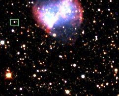
QR [NAME1] [NAME2] ( or QREGISTER [NAME1] [NAME2] )
[NAME1] and [NAME2] are the file name of the images to be register. The reference is the image [NAME1]. The QR command applied a sample translation to the image [NAME2] for superposition.
Procedure:
(1) Run the command, for example: QR M57-1 M57-2
(2) IRIS load the first image and invite you to select a star in the field. Select a insolated, bright and unsatured star. Click the right button of the mouse. Note, the position of the cross is not very critical. The goal is to identify the target. IRIS compute a very precise precision from this first localization.
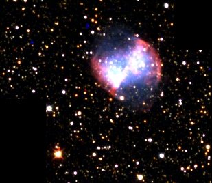
(3) The second image is downloaded. The position of the object selected in the first image if identified by a circle. This help you to find the good star in the second image.
(4) Select the object in this frame and click the right button:
(5) IRIS return the numerical value of the shift between the two images and translate the second image (this image is conserved in memory):
(6) Optionally, it is ease to check the result by subtracting the two images (for example save the translated M57-2 image in an intermediate file and use the SUB command):
SQR [NAME1] [NAME2] (or SQREGISTER [NAME1] [NAME2]
Very similar to QR command but use a spline interpolation during the geometric transformation of the [MAME2] image (QR use a bilinear interpolation - the difference is not major in the great majority of case).
QR2 [NAME1] [NAME2] (or QREGISTER2 [NAME1] [NAME2] )
Compute an affine transformation between the two images to be registered. For this it is necessary to select three stars. The mathematical transformation is:
X' = A X + B Y + C
Y' = D X + E Y + F
The parameters A, B, C, D, E, F are solved. This transform take into account the translation, rotation and change of scale between the two designed images. For example a field rotation of an azimutal telescope can easily be corrected.
Procedure:
(1) Run QR2 and select three stars in the first image. Choice is possible stars distributed on an equilateral triangle and with a large separation for a maximum precision:
(2) Select the same stars in the second image (and in the same order):
(2) IRIS return the parameters of the affine transformation and modify the second image:
See also the command COREGISTER the an automated affine registration.
SQR2 [NAME1] [NAME2] (or SQREGISTER2 [NAME1] [NAME2]
Very similar to QR2 command but use a spline interpolation during the geometric transformation of the [MAME2] image (QR use a bilinear interpolation - the difference is not major in the great majority of case).
NEW OPTIONS
A crop option is added to the video capture dialog box (Video capture... command of Webcam menu):
This in-fly crop is very useful if the goal is to acquire a very long duration AVI sequence (occulation, planetary images, etc). Another application is a function of "electronic slit" for a spectroheliograph instruments (click here for details).
The status bar return now the RGB intensities under the mouse cursor for true-color images:
The SAVEPSD command (image exportation toward Photoshop) is improved. The RAW DSLR Canon EOS 20D files are now loaded with the good dynamic range.
|