|
|
|
|
IRIS TUTORIAL
Polarization
analysis
The POLAR command computes the polarization angle and level from 3 images obtained through a
polarizing filter at angles of 0°, 60° & 120°. The syntax is:
POLAR [0°] [60°] [120°] [DEGREE] [ANGLE] [SCALE]
The three parameters [0°], [60°], and [120°] are the names of the three corresponding images. The two resultant images contain the linear polarization level (image file [degree]), and the polarization angle (image file [angle]), respectively. The parameter [scale] allows to normalize the levels of polarization degree image. If [scale]=100, the image will contain the polarization degree in percents. The intensities in the polarization angle image corresponds to degrees of polarization (between 0° and 180°). The angle origin correspond to the filter with the 0° orientation. Angles are oriented counter-clockwise.
Example:
>POLAR P0 P60 P120 POL ANGLE 100
The POLAR2 command the polarization angle and degree from 4 images obtained through a polarizing filter at angles of 0°, 45°, 90°& 135°. The four parameters [0°], [45°], [90°] and [135°] contain the names of the four corresponding images. For the next parameters see the POLAR command. The syntax is
POLAR2 [0°] [45°] [90°] [135°] [DEGREE] [ANGLE] [SCALE]
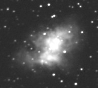
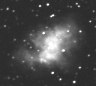
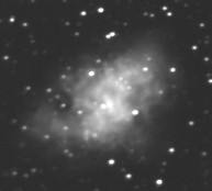
For an application, we are going to process a set of four images of the Messier 1 images taken through a polarizing filter with four position angles 45° apart. This filter was placed just in front of a CCD detector. The exposure times are identical for the four images, which are called MP1.PIC, MP2.PIC, MP3.PIC, and MP4.PIC. The offset signal has been subtracted from each of these images (see the SUB command) and they have been carefully centered to within a fraction of a pixel with respect to each other.
|
|
|
|
Dramatic change of the M1 nebula aspect for different angles of the polaroid analyseur: 0°, 45°, 90° and 135°. 60-cm telescope of Pic du Midi Observatory. The polarization is here near 30%.
Then
>POLAR2 MP1 MP2 MP3 MP4 P A 100
>LOAD P
>VISU 5 0
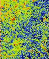
The intensity levels in P.PIC image is the traduction of the polarization degree.
Polarization
field of M1 superimposed on a grey image (left) and an isophotal image (right).
Polarization images processed with the command POLAR of Iris. The map is generated
with the command POLAR_CARTO (see
below) and it is simply added to a grey scale image or an isophotal
image (ADD
command) |
The POLAR3 is same as POLAR but for only three angles : 0°, 45° and 90° of the polaroid analyzer. The syntax is
POLAR3 [0°] [45°] [90°] [DEGREE] [ANGLE] [SCALE]
The POLAR_CARTO command creates a polarization map from an image containing the polarization magnitude and an image containing the polarization angle (in degrees). The output image is formed of small vectors whose length is proportional to the polarization degree and whose orientation is equal to the polarization angle. An angle of 0° corresponds to a vertical vector. The center of the vector is at the point where the calculation was done. The syntax is
POLAR_CARTO [DEGREE] [ANGLE] [STEP] [SCALE]
[MAGNITUDE] is the polarization magnitude image name and [ANGLE] is the angle image name. The calculation of the vectors is performed at the intersection of a mesh whose stepsize, in pixels, is contained in the parameter [STEP]. Note that the displayed result is the average of the polarization degree and the polarization angles calculated on a zone of dimension [STEP] centered on the point.
The parameter [SCALE] adjusts the length of the vectors as a function of the polarization rate. It is expressed in pixels per percent of polarization (if the polarization rate is itself in percent).
Example
>POLAR_CARTO POL ANGLE 10 30Draws a polarization map from the images POL and ANGLE. The calculation stepsize is 10 pixels, and each segment has a length of 30 pixels per polarization percentage.
|
|
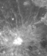
Polarization of the Moon. Left: an albedo image at the full moon. Right: the polarization map in false color at the same moment (the degree of polarization is here between 1.0 and 3.6%). |
Click
here for a typical multispectral polarimetry analysis example with DSLR.