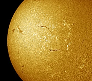
Left, 16 bits images of the solar chromosphere (image acquired by V. Desnoux with a PST Coronado). Right, image after applied >GAMMA 1.4 0.7 0.2
IRIS TUTORIAL
Sun processing
Gamma colorization
The GAMMA command adjust the RGB layers of a 48-bits images according to a power function (correction known as "gamma"). If the image in memory is 16 bits image (N&B), the conversion toward a 48 bits image is automatic. The command accept three parameters, the gamma coefficient for each channel. The typical excursion of the coefficents lies between 0,1 and 5.
Left, 16 bits
images of the solar chromosphere (image acquired by V. Desnoux with a PST
Coronado). Right, image after applied >GAMMA
1.4 0.7 0.2
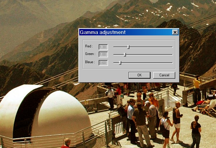
See also the command Gamma adjustement of View menu:
Simulate
a coronographic effect
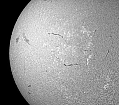
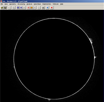
The CIRCLE and the CLICLE2 evaluate the center and the radius of a circular object (planet, sun, moon, ...). The radius value is computed for a given intensity threshold in the image. CIRCLE2 differ from CIRCLE command by the method used for identify the objet. CIRCLE use a dragged rectangular area, CIRCLE2 define the rectangle from two clicked points (more useful for large images).
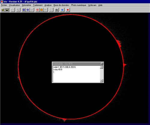
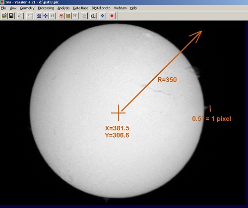
Example (on a Coronado PST Ha image of the Sun taken by Franck Vaissičre):
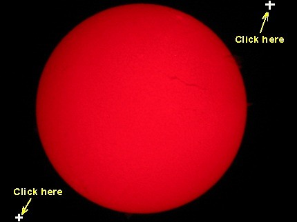
Then, enter the command:
>CIRCLE2 50
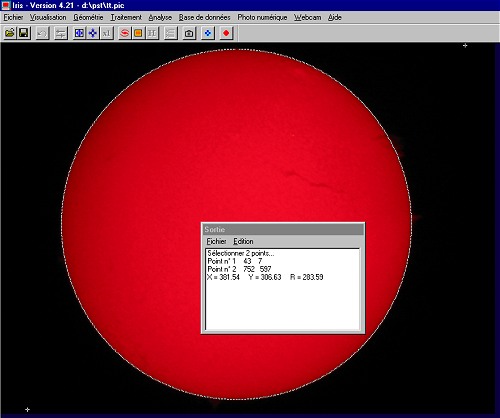
Iris return the coordinates for the disk center : X=381.54 and Y=306.63. The radius is about of 284 pixels for the outer part of the disk (at the threshold 50).
Note 1: The CIRCLE and CIRCLE2 commands are true-colors compatibles (48-bits images - but remember, use the proprietary PIC format for exploit these possibilities).
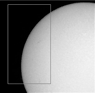
Note 2: The CIRCLE and CIRCLE2 commands can compute the disk parameters from an arc. It is useful if only a part of the objet is visible, but the precision is lower comparatively to a full disk analysis. Example:
Note 3: From the observed radius R, the equivalent focal length F of the system can be easily to estimated:
F = 2 x p x R / tan(alpha)
p is the physical size of detector pixels (more precisely, the pixel sampling), R is the observed radius of the object in pixels value and alpha is the apparent diameter of the object in degree.
For example, for the present image, the digital camera is a Canon A40. For this model p=3.3 microns=0.0033 mm. The measured radius is R=569 pixels. For the date, the apparent diameter of the Sun is alpha=0.542°. Finally, the focal length of the optical system (coronado PST + projection eyepiece + APN) is:
F = 2 x 0.0033 x 569 / tan(0.542) = 397.0 mm
Tip:
Use CREGISTER command for align a set of solar images - see
here.
The DISK1 is used for draw a dark disk on the in-memory image. The function simulate for example a coronographic effect on Sun images. The parameters are the coordinates of the disk center (X,Y) and the radius R. The syntax is DISK2 [X] [Y] [R]. For example:
>DISK1 381.5 306.6 283.6
The DISK2 function is the opposite of the DISK1 function, the outer part of the defined disk is masked.
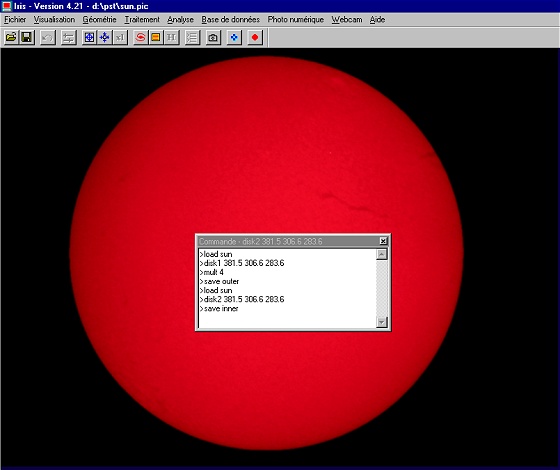
The simultaneous use of DISK1 and DISK2 is a solution for enhance the aspects of prominance on the Ha image. For example (the intensity of outer part of the sun image is multiplized by factor 4 - try some values):
>LOAD SUN
>DISK1 381.5 306.6 283.6
>MULT 4
>SAVE
OUTER
Now, use the DISK2 command for isolate only the sun disk image:
>LOAD SUN
>DISK2 381.5 306.6
283.6
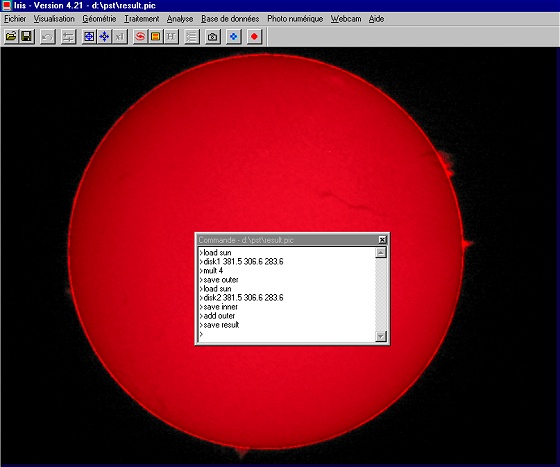
Finally, add the inner and the outer images:
>ADD OUTER
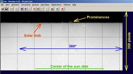
The REC2POL command transform natural "circular" aspect of sun chromosphere's to a polar representation (an axis is the distance from the center of the disk and an axis represent angular values). The syntax is REC2POL [X] [Y] [R] [SCALE (deg./pixel)]. (X, Y) are the coordinates of the disk center image in pixel. [R] is the max. radius in pixels of the polar representation. The [SCALE] parameter is the number of degrees by pixel unit in the final image (typical slect values from 0.5°/pixel to 0.1°/pixel).
Here a full example.
The processed image is taken with a digital camera. Only the red channel contain information about Ha wavelength (some time information is also present on the green and bleue channels, but the color balance is very dependant of the dye filter technology used in the digital camera). First, it is truly recommended to isolate the RGB channels from the 48-bits images and use only the red frame for chromospheric studies. Run the RGB separation dialog box (Digital photo menu) for extract the R layer:

or run the console command:
>SPLIT_RGB R G B
Load the red image:
>LOAD R
Run the REC2POL command. The parameters are X=381.5, Y=306.6, R=350, SCALE=0.5°/pixel
>REC2POL 381.5 306.6 350 0.5
Here, the result REC2POL command
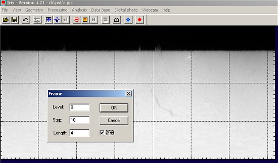
For a more classical representation (i.e. horizontal angle axis), use MIRRORXY command for rotate (or open the Flip dialog box of the Geometry menu). You can also draw a grid (here a tick for each 5°) - Grid dialog box of View menu :
The signification of this image:
See also the cartographic features of IRIS (MAP command).
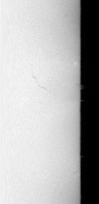
The LFILL command (syntax: LFILL [X0] [VALUE]) mask the left part of an image relative to the [X0] coordinate. Iris give the level [VALUE] to the masked area. The RFILL command (syntax: RFILL [X0] [VALUE]) mask the right part of an image relative to the [X0] coordinate. First, measure the x-position of the sun limb in the polar representation:
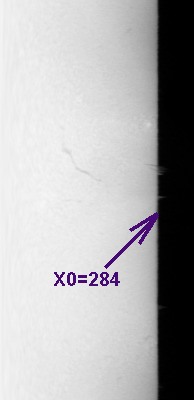
then:
>LFILL 284 0
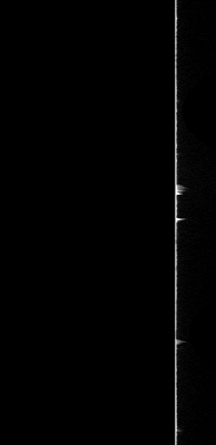
Finally perform a rectangular to polar transform (REC2POL command):
>REC2POL 381.5 306.6 350 0.5
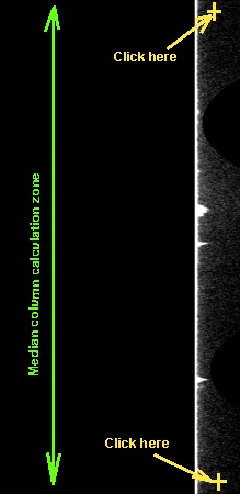
Now with the L_EQUAL command remove the parasitic gradient around the sun limb (light diffused by the optics and atmosphere) for enhance faint prominences. For each column of the image, Iris substrat the median value computed between two points selected with the mouse. Example, start from the polar transform:
>L_EQUAL
then
|
|
|
|
|
Run the L_EQUAL command. Select two points along the vertical axis (click with the mouse). |
After the second click, Iris remove the radial gradient around the sun. |
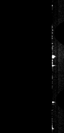
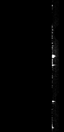
Th aesthetic, the non-significant part at right is masked: RFILL 319 0 |
Run the REC2POL command and display the result (high contrast visualisation):
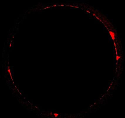
Tip: For a pure red representation of the prominences, run for example the sequence:
>SAVE
R
>FILL 0
>SAVE G
>SAVE B
>TR R G B
Tip: POL2REC2 is very similar to POL2REC. The syntax POL2REC2 [X] [Y] [R] [POS. ANGLE] [SCALE (deg./pixel)]. The added parameter [pos. angle] offer the possibility to adjust the origin of angle in the rectangular representation. You can take into account the apparent orientation of rotation axis of the sun for example. The angular value is given in degrees (the default value of the POL2REC command is [pos. angle] = -180°).