IRIS TUTORIAL
Cosmetic corrections
Manual hot-spot removal procedure
(1) Select the part of the image containing hot-spot to erase (drag with the mouse):
then
>MAX 3
The three most brigthness spot are erased (Iris use an iterative procedure for detect the spots):
Large structure can be aloso erased. For example, the cosmic ray impact:
>MAX 120
The symetric command is MIN, for erase dark spot.
Repair a column or a line
Note a deficient column at coordinate X=148:
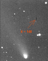
then
>REPAIRX 148
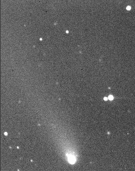
The result
For correct a line use REPAIRY command.
Erase dust
The ERASE command clean the information located inside a selection box. An interpolation of the central zone is carried out by using pixels located on the periphery. The texture of the erased area is preserved for a neutral rendering. This command can be used for example to erase residual dust umbra in the image.
|
|
|
Left, an image affected by the presence of dust in the optical path. Middle, selection of dust zones. Right, the result after sucessives run of ERASE command.
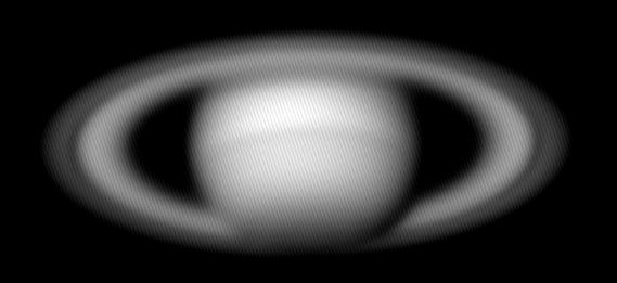
Periodic pattern noise removal
FFT (Fast Fourier Transform ) functions of Iris can be used for remove the fixed pattern noise of an image.Consider this Saturn image from a webcam (Source Sylvain Weiller). Periodic parasitic electrical noise is clearly visible
The command for direct FFT is FFTD,
the command for inverse FFT is FFTI.
First of all the direct FFT
>FFTD X Y
The two parameters are the file names for the modulus and argument of the resulting FFT transform (the result is in polar coordinate representation). The modulus is displayed on the screen.
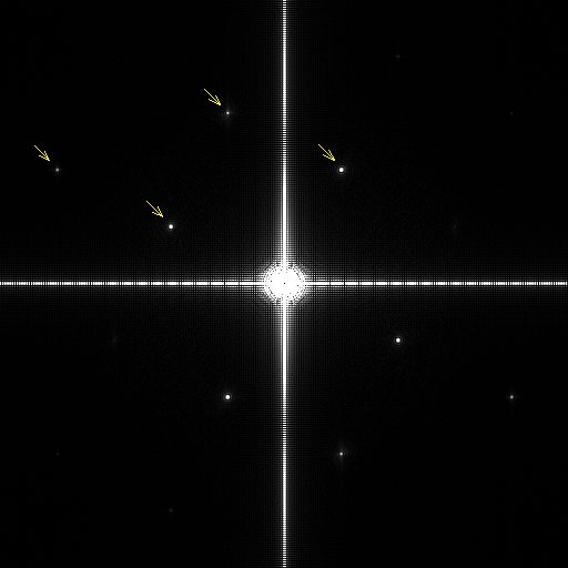
The two-dimensional FFT can provide information in the frequency domain in both the horizontal and vertical directions and, in particular, will indicate any modulation of a parasitic signal. The arrow indicate the peak frequency of the fixed parttern noise: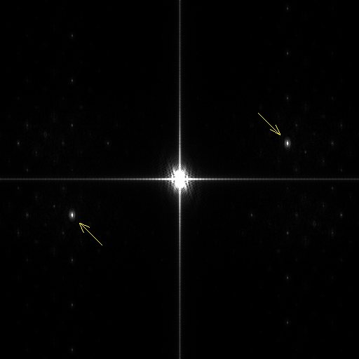
Now, mask the noise peak by the use of FFILL. The command fill with a given value two area symmetric with regard to the x-axis and y-axis. For remove the principal parasitic peak drag a small rectangle around one of the peak...
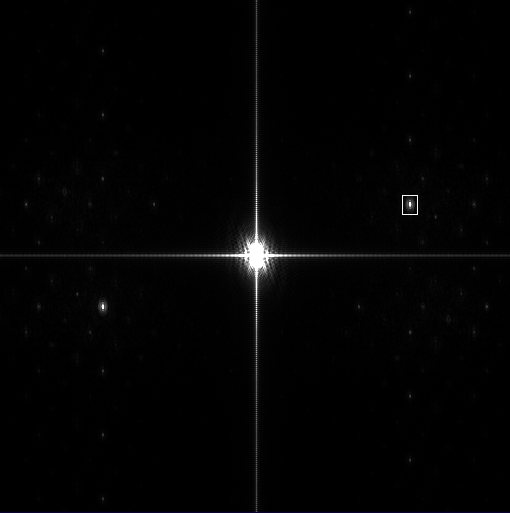
.. . then
>FFILL 0
Save the modified module component of the FFT (an important step):
>SAVE X
Now compute the inverse FFT
>FFTI X Y
The result is now a very clean image

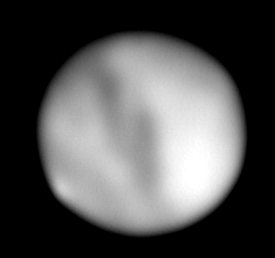
Another example, a webcam image of Mars planet (Source Pierre Thierry):
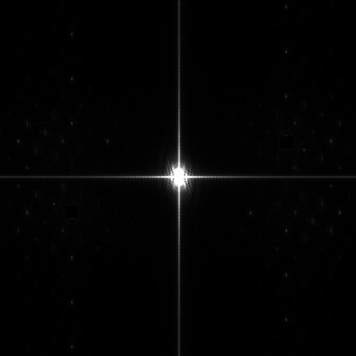
Many parasitic frequency are visible in the frequency domain (after FFTD command):
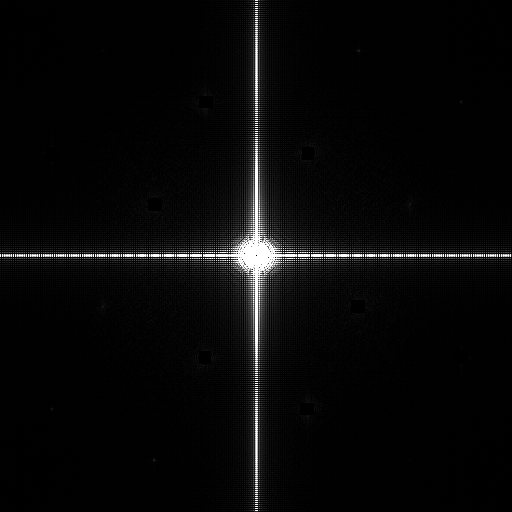
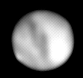
And now the rectified image:
Some related functions:
FPOLREC transform the frequency domain images from polar to rectangular.
Syntax: FPOLREC [MODULUS] [ARGUMENT]
FRECPOL transform
the frequency domain images from rectangular to polar. Syntax:
FRECPOL [REAL PART] [IMAGINARY PART]
FCORREL
compute
the cross-correlation of images #1 and #2. Syntax:
FCORREL [IMAGE #1] [IMAGE #1] [COEF].The [coef] coefficient is an intensity
scale factor for the result. Example:
>FCORREL MARS1 MARS2 1
FFTD2 calculate the direct Fourier transform of a sequence of images. Syntax: FFTD2 [ IN ] [ MODULE ] [ PHASE] [ NUMBER ]
FFTI2 calculate the inverse Fourier transform of a sequence of images. Syntax: FFTI2 [ IN ] [ MODULE ] [ PHASE ] [ NUMBER ]