The idea behind this camera to be able to readout all kind of CCD, as the
following 7 CCDs for instance :
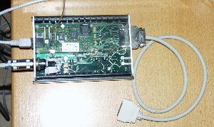
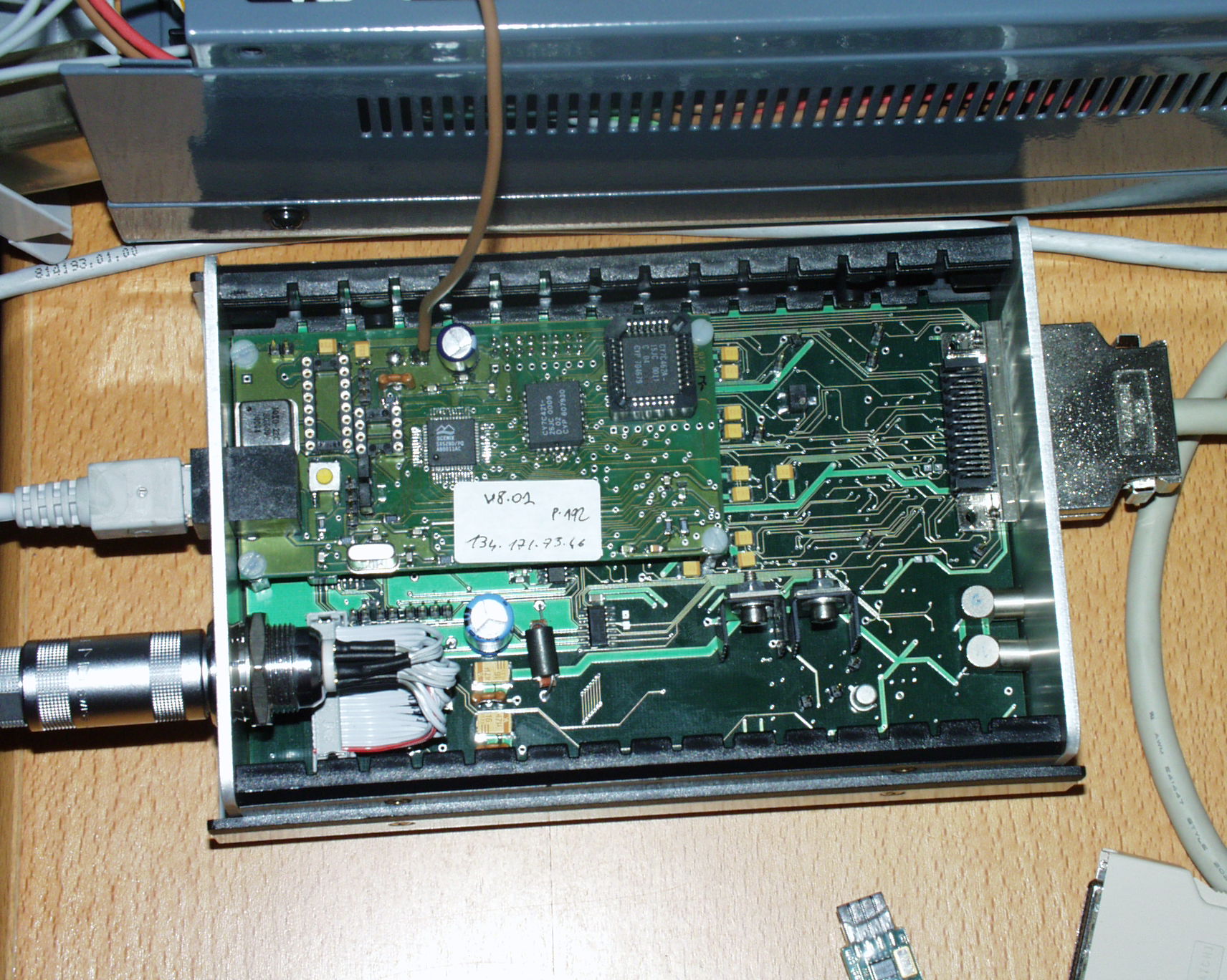
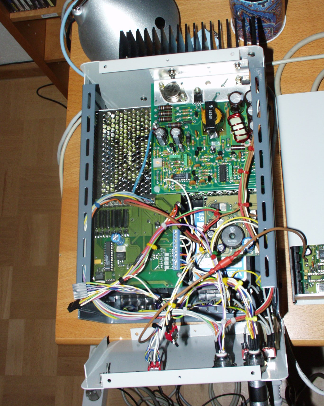
The main box
This box contains the main Chungara's controler board, the cables
that are tied to it are : the ethernet cable, the power supply cable, the
clock/bias cable and the two video cables. This box shall remain closeby to
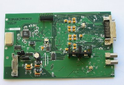
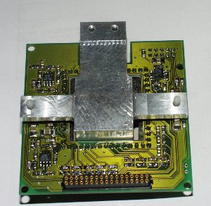
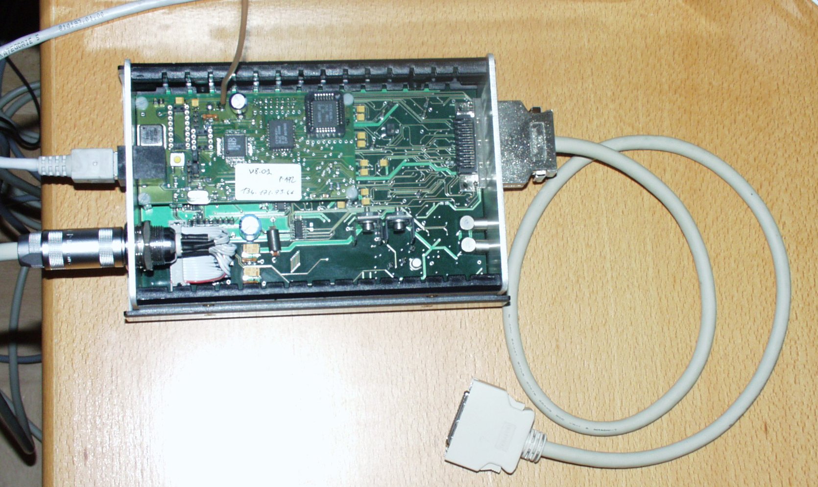
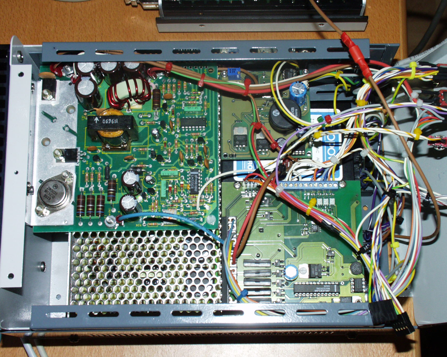
the CCD head (max 50cm). The next image shows the top view of the opened controler
box, the ethernet board is located on top of the main board (top-left). The
analog clock and bias lines are driven to the head with a SCSI like cable.

Main box(160x110x50) top view, opened, as scale the white RJ45 connector
connected to the box.
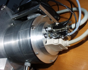
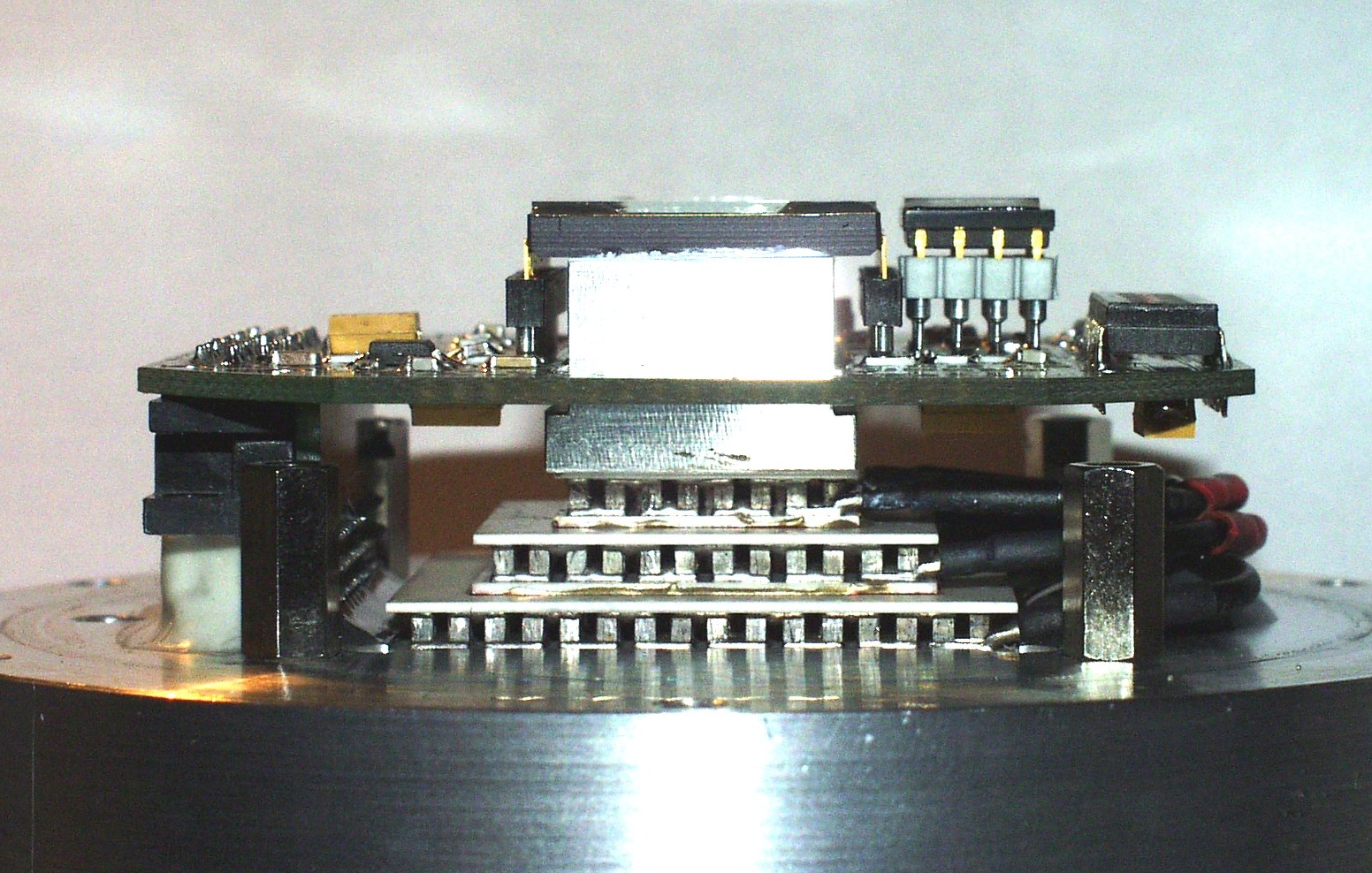
how the cables reach the head : clock-bias cable, peltier power cable and
the two video cables.

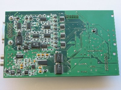
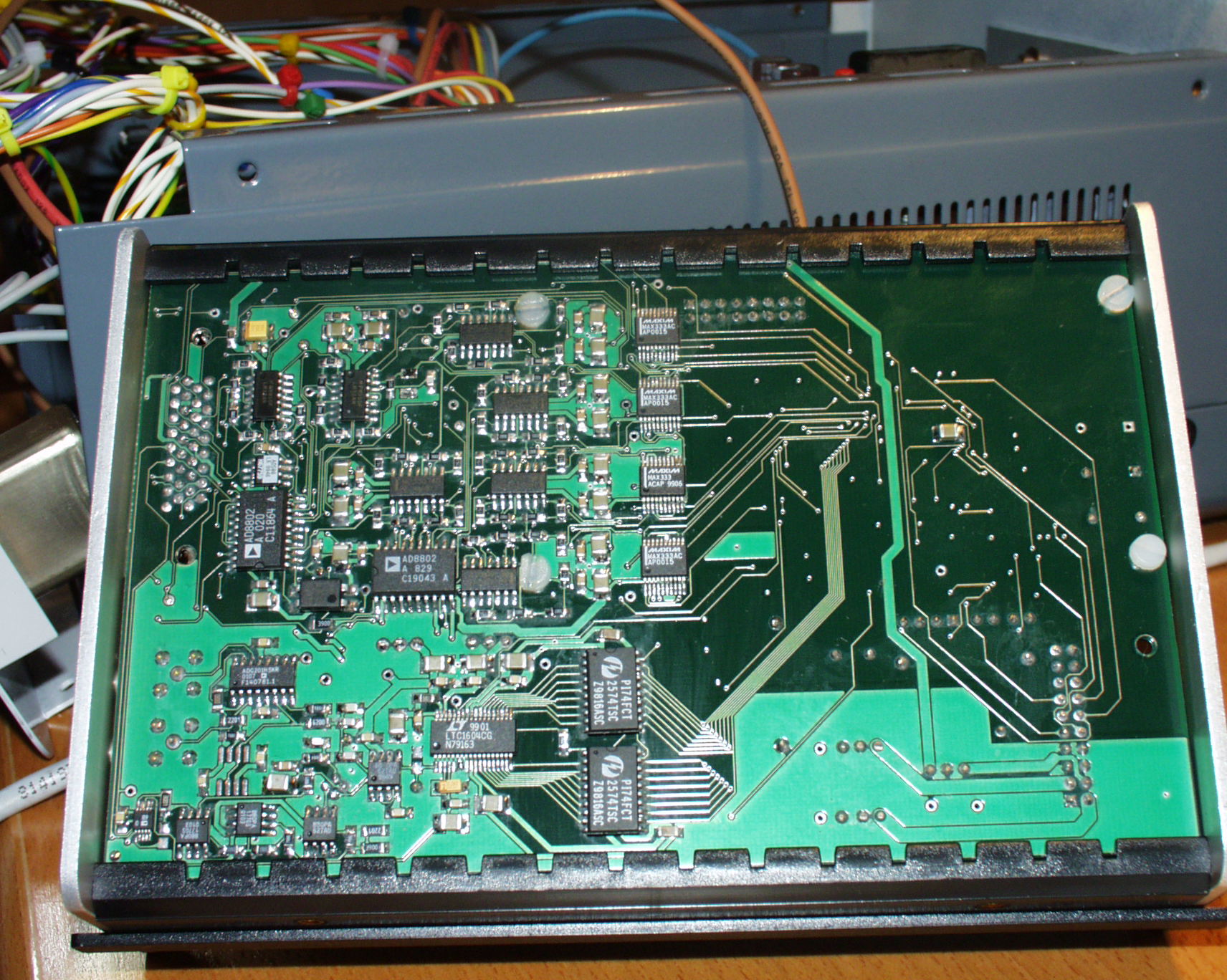
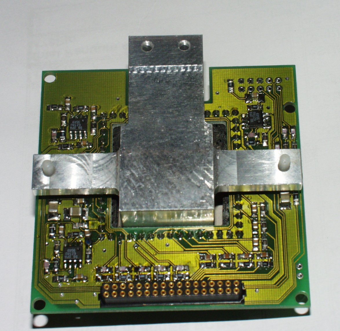
Main box upside-down showing components for clock/biases generation and video
chain, this board is a 4 layer board with SMD parts.
The power supply
The power supply is intended to supply the main controler box
and the CCD heads with :
-
2x2K, TH7899M Thomson
-
1x1K Thinned, Marconi 47-10
-
1x1K, Thinned TK1024 SITe
-
Kodak Kaf1600 and 400 family
-
indeed most CCD in the market, in that case just a redesign
of the head board (PCB) is necessary.
LORAL 2Kx2K
2048x2048, 14um pixel, Backside thinned, MPP CCD

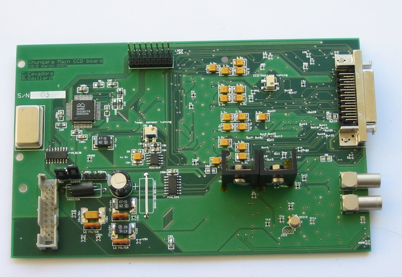
Loral 2x2K CCD head board.
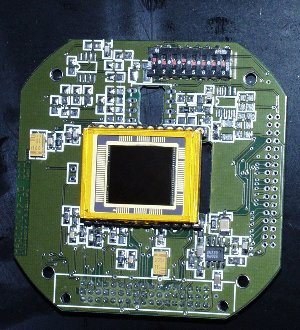
THOMSON TH7899M
2048x2048, 14um pixel, Frontside, MPP CCD
TH7899M CCD head board.
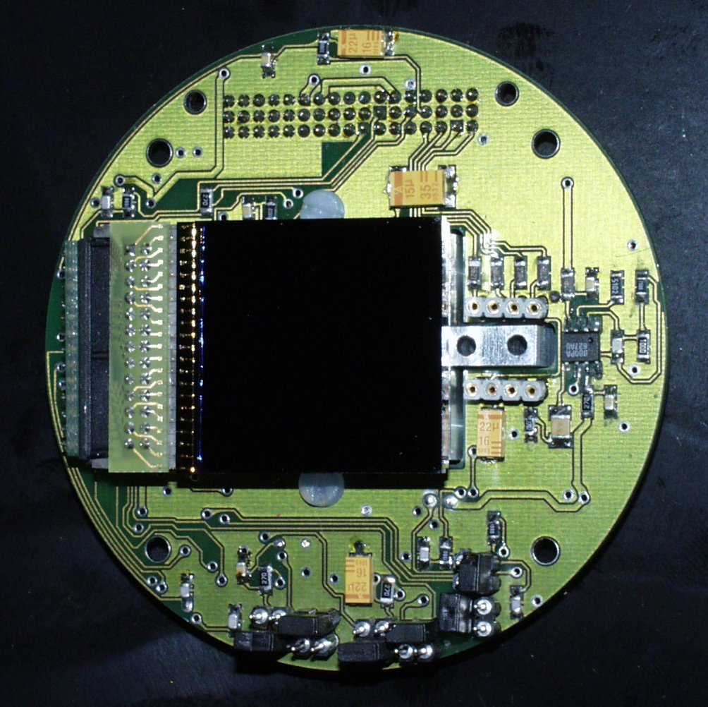
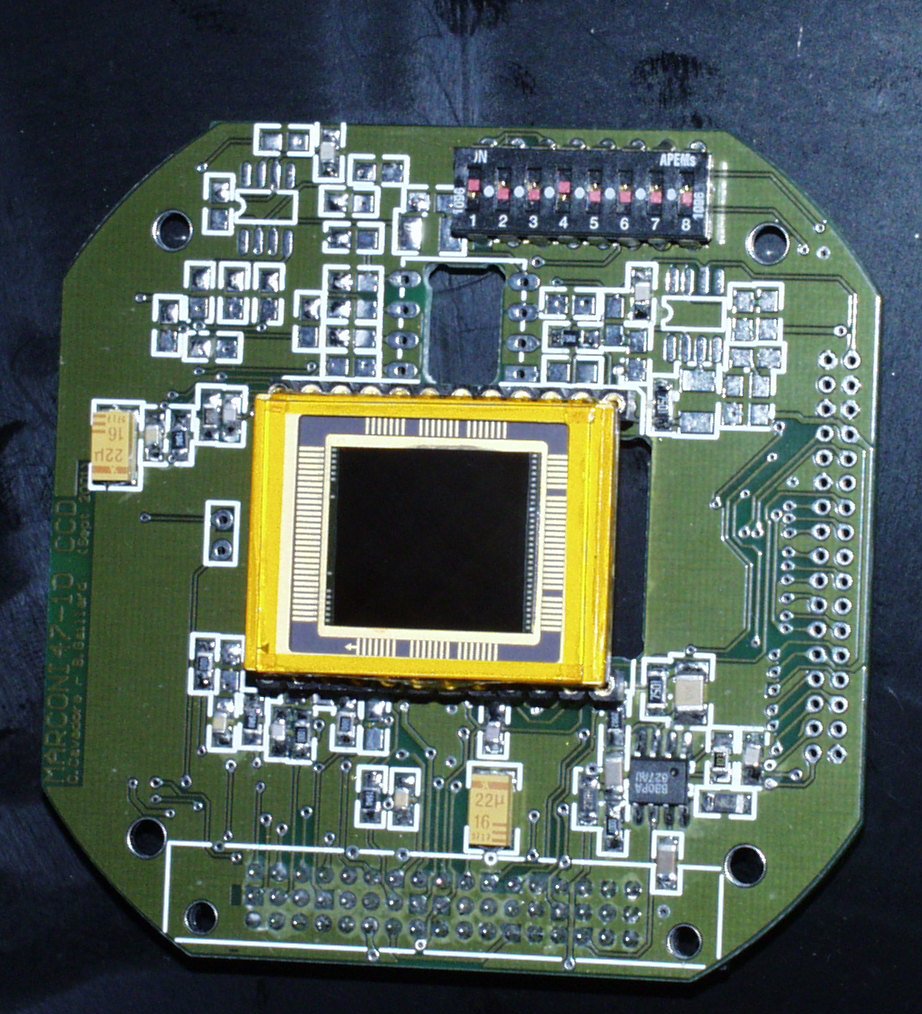
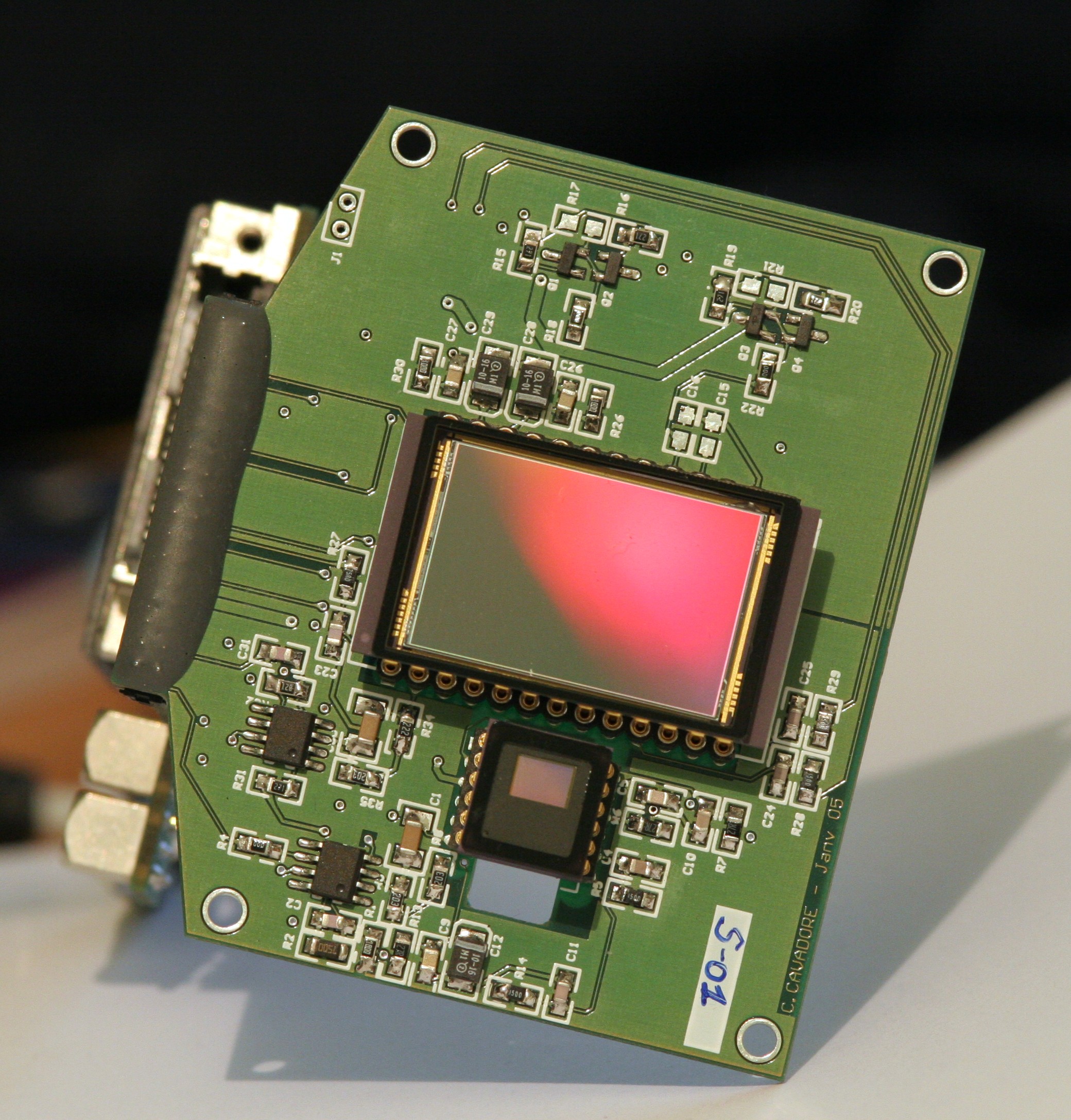
Marconi47-10
1024x1024, 13um pixel, Backside thinned, MPP CCD
Marconi47-10 head board.
Some tests have been achieved using this setup, see
here and concerning sky tests, have
a look here.
Readout noise achieved with this CCD is around 7.5e- at 75Kpx/sec, the
whole CCD is read in 14sec. The whole guiding CCD (360x240 10 um pixels)
is read in 0.3sec
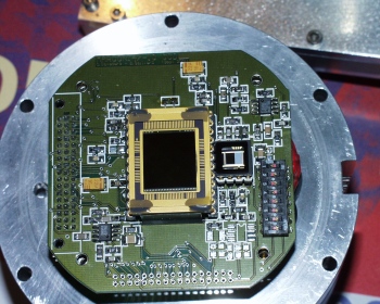
Marconi47-10 head board, with the guiding TC255P CCD, located a 17mm
from the main CCD optical axis.
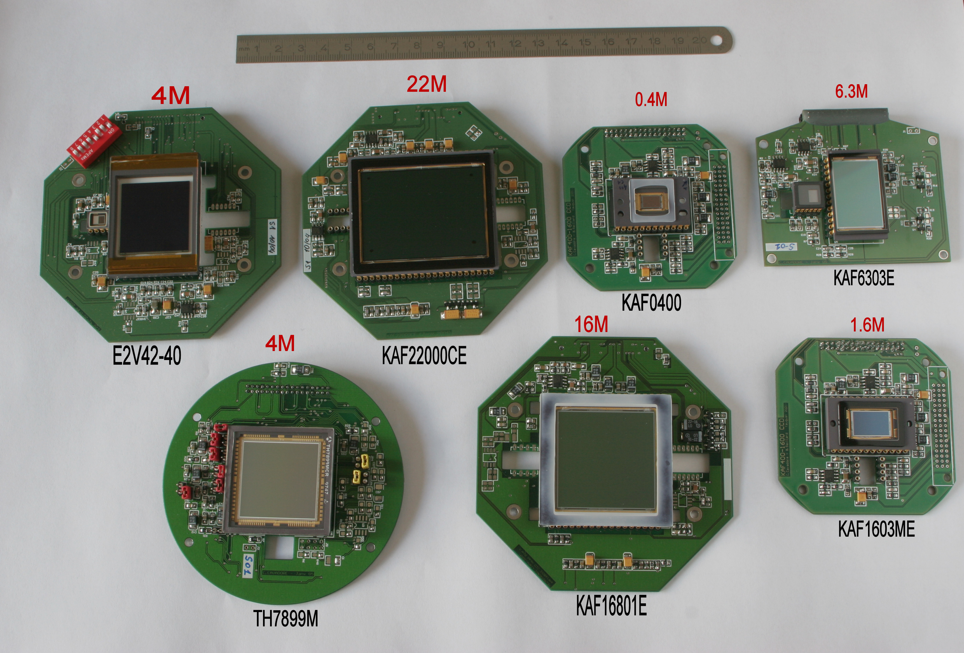
Kodak KAF0400/1600ME/3200ME (any kind)
Head PCB has been done and this device is working successfuly !
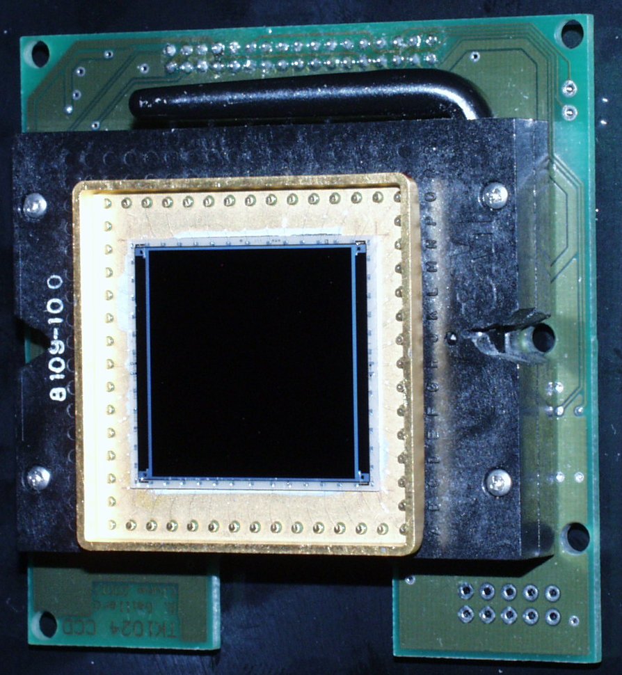
TK1024 or Site1024
1024x1024, 24um pixel, Backside thinned, MPP CCD
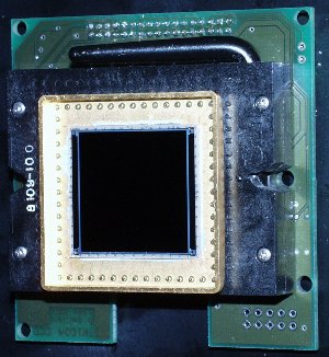
Tk1024 CCD head board, upside down, the common interface is the 34 pin
black connector.
KAF16801E
4096x4096, 9um pixel, Kodak CCD, this device has 16 millions
pixels and can be read out within 58sec. The device has 36x36 mm sensitive
surface !!
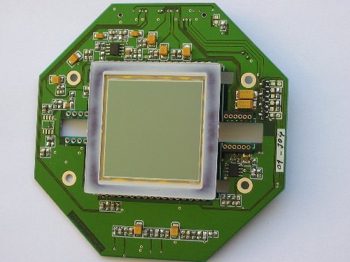
The board is a 100x100mm 4 layer PCB. The guiding CCDs (TC237
or TC255) slots can be seen.
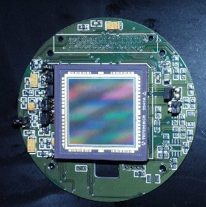
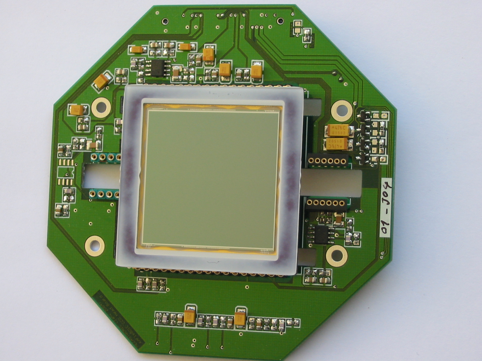
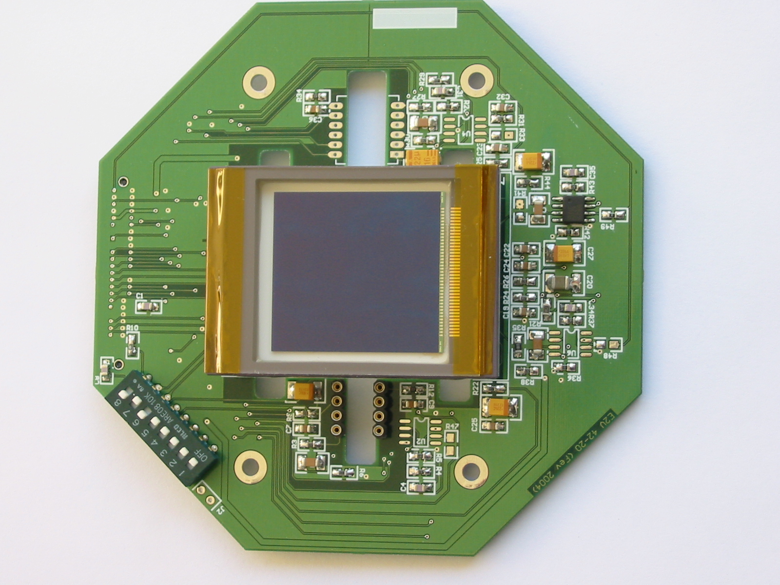
E2V 42-40
2048x2048, 13um pixel, high performance low noise backside
illuminated CCD, E2V (marconi CCD), this device has 4 millions pixels. The
sensitive area is 26.6 x 26.6 mm.
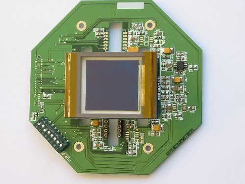
The board is a 100x100mm 4 layer PCB. The guiding CCDs (TC237
or TC255) slots can be seen.
KAF 22000CE
4080x5440, 9um pixel, RGB color array, this device has 22
millions pixels.The device has 50 x 38.8 mm sensitive surface... this is really
huge !
The board is a 100x100mm 4 layer PCB. The guiding CCDs (TC237 or TC255) slots
can be seen.
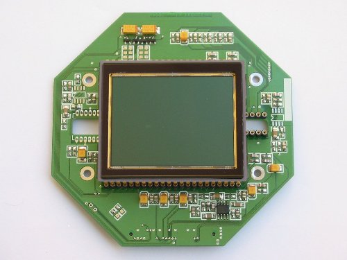
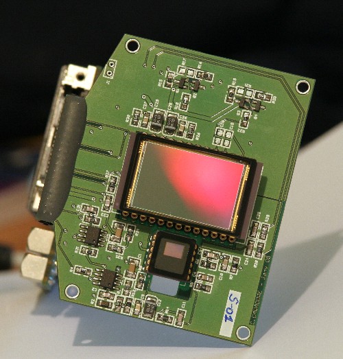
KAF 6303E
3072 x 2048 pixels, 9x9µm : this
27.6 x 18.5 mm device
WARNING :
This cameras CANNOT be manufactured by mecastronic as stated in this page, no contract has been set, this company is just violating copyrights and is unable to produce them ! So do not buy anything from them. No company is going to manufacture them, this product is discontinued for ever and not available for sale.


