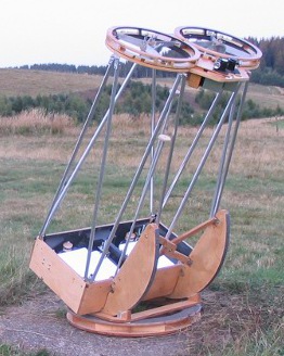
The program should be easy to use as soon as you are familiar with the kind of binocular telescope it is aimed at. The drawings and computations correspond to a binoscope with a rotating secondary cage. You can find an example on the image below (my 360mm binoscope). Other examples of these binoscopes can be found on these web pages : http://lerch.yi.org/atm/ , http://www.binoscope.co.nz/ .
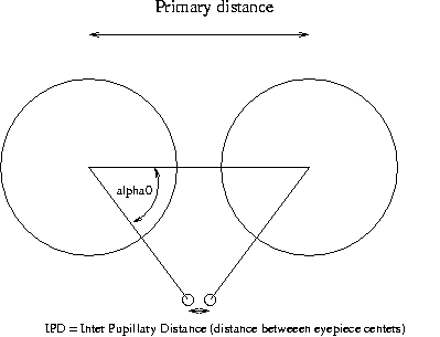
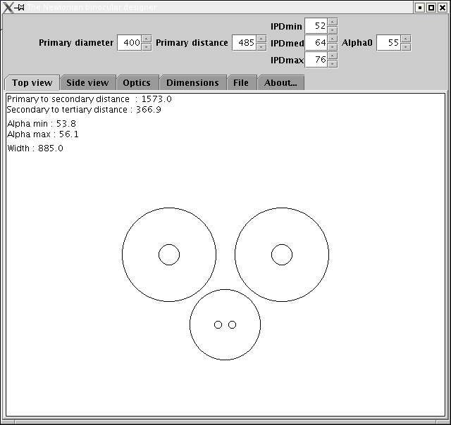
IPD stands for Inter Pupillary Distance (the distance between eypeiece centers). IPDmed is the average value of the IPD. IPDmin and IPDmax are the smallest and the largest value that should be reachable by rotating the secondary cages. The angle alpha0 corresponds to IPDmed. Once you have chosen both alpha0 and the range of IPD you want to be able to use, the program computes by how much you will have to turn the secondary cages to reach IPDmin or IPDmax. The corresponding alpha angles are displayed in the top view and side view.
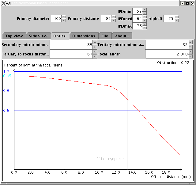
All the distances between mirrors start from the optical center of a mirror to the optical center of the next mirror. In the optics tab, you can view how much light reaches the focal plane depending on the off axis distance. Note that it is not possible to reach 100% illumination even at the center of the field because of secondary obstruction. The maximum illumination (which takes secondary obstruction into account) is displayed in cyan.
In the top and side view you can zoom in or out by using the mouse wheel.
A new parameter called "fold-angle" has been added in version 1.2. This parameters allows to study folded configurations where the secondary miror is not at 45° with reference to the optical axis of the primary. This configuration can be useful for large binocular telescopes in order to reduce eyepiece height. I don't know of any folded binocular newtonian telescope being built anywhere on earth. But with binoculars becoming larger and larger (20", 22", and even 24"), there may be some interest in this function. By default "fold-angle" is set at 0°: this is the standard configuration. If the telescope is aimed at the zenith and fold-angle=0 then the optical axis is horizontal afer the secondary. Fold-angle refers to the optical axis. If you increase fold-angle by 1° then the optical axis after the secondary miror has an angle of 1° below the horizontal plane (and the secondary miror has been rotated by only 0.5°).
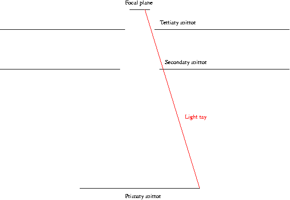
Please note that the computation of the curve showing the illumination versus off axis distance is not exact. It should be a good approximation but I recomend that you double check the results before ordering or grinding the mirrors. A better computation will be available in a future version. If you want to know how it is computed, here is a small explanation. The program divides the primary mirror in small squares (10000 squares are currently used). For each square it computes if this part of the mirror is visible from the focal plane. To simplify things I assume the secondary mirror and the tertiary mirror are circular openings in planes perpendicular to the optical axis as shown on the figure below (the light ray shown in red does not pass through the secondary mirror). Thus decentering of the plane mirrors are not taken into account as they should be.
collimation simulation
magnified view of the tertiary and eyepiece
- source code released as open-source under the GPL license
- folded configurations
- improved user interface
- secondary cage diameter to prevent vignetting for 1"1/4 or 2" eyepieces
first public release