Improving the Hedrick focuser on a PW CDK12.5
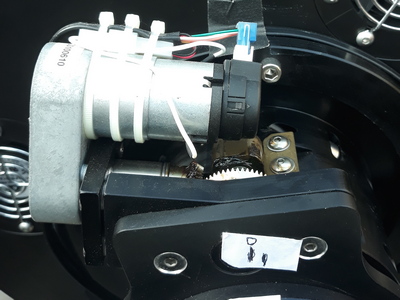
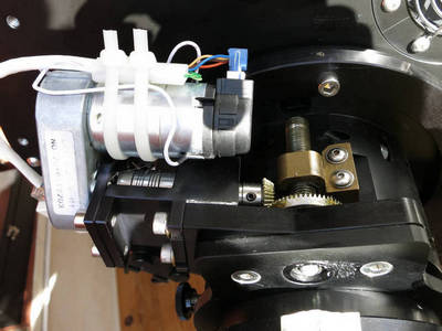
The Hedrick focuser on a Planewave CDK12.5
This crayford type focuser is motorized by a 90° bevel gear linked on the draw tube and linked to the main side by a screw itself linked to the larger gear. The motor is rotated the small gear via the output shaft of the reductor.
Problématique
The small pignon of the bevel gear is attached at th eend of an extension shaft screwed on the output shat of the reductor body. This design option minimize the numbesr of parts and the cost but cause a radial torque on the shaft while it rotates. The internal bearing of the output shaft takes the full strain from the small gear. The wear of the bearing increase overtime with the effect of increasing the root clearance in the bevel gear. The downside is that the repetability/accuccarcy of the positioning decrease in the same time.
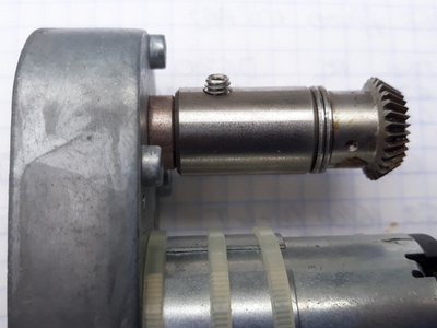
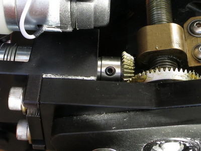
Original set : Motor-Reductor-Extension shaft-Small bevel gear
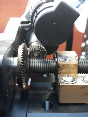
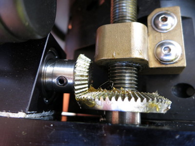
Furthermore, by the PW design, the centers of the primitive cones of the two gears are not concurrent with an offset up to 1,5mm for a 4,5mm teeth contact lenght.
PlaneWave factory setting - Note the large gear offset
The consequences are :
• unaccuraccy in the moving steps IN/OUT,
• a poor repetability of the absolute position of the focuser,
• a systematic shift of the best focus "electronic" position,
• an unreliable autofocus,
• wear on the gear tooth and also on the redcutor bearing,
• a torque transmission not optimized.
Solution
The main idea is to take in account the original design of the focuser that way to minimize the complexity, the risks and also the costs. And at last provide an ad-on assembly for any CDK12.5 owner who want to improve its telescope.
The design focus is on a new motor bracket on the one hand and on the extension shaft/gear on the other hand.
My solution is a double ball bearing bracket carrying an internal shaft with on one side the small gear and a flexible coupling linked to the shaft reductor on the other side.
This assembly will eliminate any radial pulse from the small gear and will ensure a fixe position from the large gear. The flexible coupling will releive any stress and wear on the reductor internal bearing.
New assembly with its roller bearing bracket and felxible coupling
The coincidence of the primitive cones gives the axial position of the small gear. It is ajust by a progressive and iterative pushing of the roller bearing/shaft/gear assembly in the braket bore.
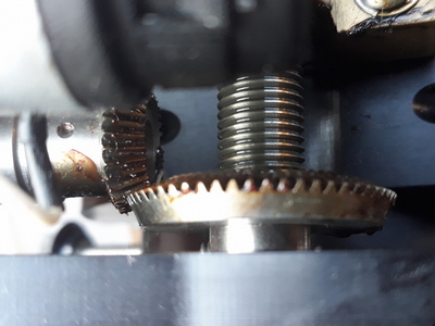
The perfect coincidence is judge visually with a nice side alignment of the two gear.
Small gear axail adjustment vs large gear -Side on the same level
The gear radial play is set step by step by a stack of 0,1mm shim thickness coming from an aluminium tape.
Radial setting of the small gear by a shim stack
When all the settings are well done without any large play nor any hard spot the bracket is locked in position via two CHC 10-32 UNF-3/4 screwed on the original PW face.
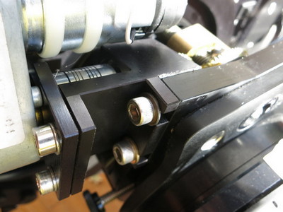
Two CHc 10.32 UNFx3/4 to lock the bracket
- If OK, lightly grease the gear and turn it several runs to spread the lubricant.
- If NOK (hard spot), adjust the position by adding one another shim and test again.
The flexible coupling is then fitted but not thightened on the the bearing shaft. The reductor body is screwed on its support via 3 TF M3-6 screws then the output reductor shaft is put in the coupling device. The support is then fixed on the bracket by a set of two screws.

Flexible coupling Ruland PCMR 19-6-6-A
The flexible coupling is axialy set along the two shafts (the radial slots must be not pressed nor too much expanded). Finally, the coupling is screwed on the two shafts.
A full calibration of the focuser has to be made along the PW procedure.
Résultats
Before and after the new bracket, the focuser is tested along the the IN and OUT side with steps of 100µm. The response to the consigne done with PWI software is checked with a 1/100mm dial indicator.
The scope is positioned horizontaly and the focuser hold my standard imaging train mainly composed of one STL CCD camera, an homemade OAG+Sbig remote guiding head camera, a Takahashi rotating collar. The overall load is about 4,2 Kg.
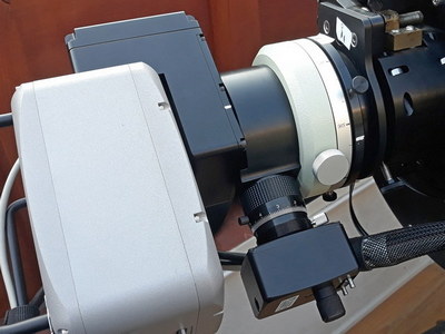
The imaging train on the Hedrick focuser
The test protocole is the following one :
- Focuser on its focus position (9,5mm for my setup)
- Output of the focuser (OUT) with 10 steps of 100µm
- Return of the focuser (IN) with 6 step of 100µm
- Dial comparator setting to "0"
- Return of the focuser (IN) as per 4 x 1 step of 100µm, in each case reading on the dial comparator of the real move of the focuser
- Inversion de sens : Output of the focuser (OUT) as per 4 x 1 step of 100µm, in each case reading on the dial comparator of the real move of the focuser --> back to the starting point (0 dial comparator).
The procedure is repeat 3 times and the mean value of each step IN/OUT is calculated.
The PW setting is the factory one with conversion fcator 115.134 step encodeur/µm. The backlash is set to 0.
Below the mean values in the Excel table and the correponding graph :
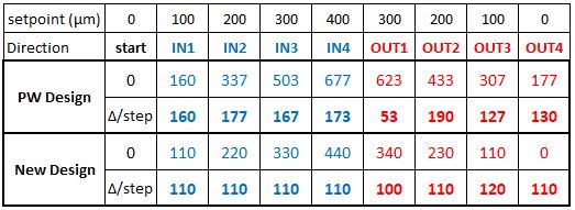
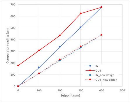
With the original design, it may be noted the large amount of shift as the focuser reverse from IN to OUT. The starting point is shifted from about 180µm... For a 100µm setpoint, the mean real step is 147µm +/- 87 µm (2s).
With the new design, the IN and OUT move are perfectly collinear and the back position is only shift by less than 10µm. For a 100µm setpoint, the mean real step is 110µm +/- 10 µm (2s).
Conclusion
The Hedrick focuser is a strong focuser able to support heavy load without any lflexions. With this upgrade, it corrects a design error and therefore greatly improve its reliabilty, accuracy and repetability.
This new assembly is adaptable to any CDK12.5 by recovering the small gear and the motor/reductor assembly. The extension shaft and the gear are screwed but also glued with a bit of Loctite glue. Their disassembly is a bit difficult and may require to heat a bit the parts to help.
Thanks to SkyMeca for their responsiveness and the great mecanical manufacturing according to my drawings.
The overall cost price of the complete modification is 210 Euros.
Enjoy !
On request, I can provide the part drawings.