G11 Modification : redesign of the RA worm block
Initial condition
The RA or AD drive is a worm-gear system mated to a stepper motor through a reduction gear box. Tracking quality is dependent on the machining, the performance of the motor/gearbox and play between gear and worm. The latter is mounted into two ball bearings each in a separate housing (block) tied to the base plate by hex screws.
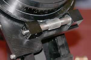
Note the two independent blocks housing the ball bearings.
Access to the worm is straightforward: all it takes is removing the aluminum cover held by two screws. Then once can decouple the worm from the motor: remove the motor by unscrewing the two retaining screws. The worm link is made of three pieces: a flange tightened on the gearbox axle, another on the worm and the Oldham coupler in between (make sure you do not lose it).
Issues begin as soon as a fine tracking adjustment is needed. The two blocks need to be loosened, then grabbed between two fingers and moved closer to one another of further apart to set the right amount of play. Once this is done, the blocks' holding screws need to be tightened. However, as soon as this is attempted, the block rotates due to the torque. The worm moves slightly and the adjusted play is no longer correct. And then there is the second block to tighten
Moreover, this design does not guarantee a correct axial play. One block can be slightly askew with respect to the axis of rotation of the work and force a stress on the bearing
The height of the worm with respect to the gear was verified. The original Losmandy design is too low by 0.2 mm with respect to the exact rotational plane of the gear. Consequently I added two 0.2 mm thick metal shims.
Note the two 0.2 mm shims above the worm blocks.
I then decided to redesign this system with the following goals :
• Separate the bearing axial adjustment from the gear mesh adjustment
• Improve the mesh adjustment and its setting
• Add a bearing axial adjustment
• Modify the motor coupling without play
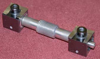
New worm housing
I designed a single worm block that includes the two ball bearings, the worm and an axial play adjustment. The gear mesh is done by moving the whole unit. The location setting is provided by the two original hex screws.
Mouse over to open the window.
This housing has two opposite windows : one to obviously allow the worm to contact the grear, and the other to provide easy access for periodic addition of grease. A cover closes the second opening.
The axial pre-load is done by a threaded ring. Too tight and the worm is stuck. Too loose, the worm can move axially and give rise to a significant backlash during guiding corrections.
The ball bearings have been changed. They are mounted with a tight fit to the worm and looser in the housing. This enables the unit to be assembled and allows the axial preload to be done though the outer raceways.
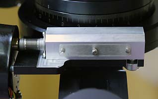
The height of the worm with respect to the gear has been verified. The original Losmandy design is too low by 0.2 mm with respect to the exact rotational plane of the gear. Consequently I added two 0.2 mm thick metal shims.
The new housing, taller than the older blocks, compensates for this but this required milling down the base plate by 1 mm
The link between the gearbox and the worm is done with a bellows coupler (stainless) devoid of axial play.
The plans (.pdf) are avialable here.
Résults
Building and adjusting the unit is child s play. The separation between adjustments is a pleasure that is also intuitive. Tightening the housing has no impact on tracking performance and remains stable over time. The RA backlash is down to a minimum. The motors do not stall in spite of a 25 kg load (C14 plus accessories). With the older system, I had to change the RA original Hurst motor. Today's motors are made by Saya.
What about the tracking?
With the older blocks, I had a 10 peak to peak PE, or ±5 arc-sec. This was not terrible for this 1995 mount fitted with the original worm.

Mouse over to see before and after.
With the new housing, PE has been reduced to 6 arc-seconds peak to peak or ±3 arc-sec, a 40% reduction.
The improvement bears mostly on the reduction of the 4 arc-second eccentricity. It was the intent of the redesign to guarantee a perfect axial alignment between the bearings. The worm's eccentricity still remains with is rapid 4 arc-second jumps every 30 seconds, typical of the Losmandy mounts. These errors come from the worm machining quality. The gear box does not generate this periodic error.
Thanks to Olivier Prache (NY) for the translation of this page.