Improvement of the JMI NGF-XTc 3" focuser
Problema
The JMI NGF-XTc is a crayford focuser type produced by JIM's Mobile in the USA and specially designed for a Cassegrain telescope. It is rated as being able to handle 8 lbs of equipment, up to 18lbs when motorized. I purchased one to hold my 3,7 kg imaging train composed of a STL4020M camera, an AOL and a Takahashi Camera Angle Adjuster. The large 3" I.D. (76mm) produces no vigneting on the optical path from the C14 baffle (54.5mm). A Robofocus motor is mounted to finely drive the focus from the computer.
Unfortunately, I found a serious issue on this focuser while making the flats. The latter's never overlay perfectly with the raw images. The shift is substantial, up to dozens of pixels. My flats are made with a light box installed on the top of the OTA, turned vertically for this operation. As the mirror is fixed by a locking device, the problem should only come from a shift between the camera and the optical axis. This shift appears between the acquisitions where the scope is inclined toward the object and the flat operation with a scope set vetically.
I have soon suspected flexures coming on one hand by the locking system on the rear cell of the C14, on the other hand by the drawtube itself.
If the focuser bend on load, the perpendicularity of the chip with the optical axis will change during the night according to the scope position. As a result the flats made at the end of the night should never match the raw images. Moreover, the collimation will also change with the tilt of the camera.
To be sure, I decided to firstly do some measurements and secondly find a solution to correct this issue.
The tilt measurements
A 3mm range dial indicator (grads 1/100mm) is mounted rigidly on the C14 optical tube. The motor of the robofocus is switched on and the brake of the focuser is thightened. The load applied on the drawtube is about 3,7 kg (STL4k+AOL+Takahashi CAA+adapters).
First, a measurement run is made from the camera. The indicator point is put on the STL main body to the CCD level. The distance of the contact point from the rear face of the focuser is 150 mm.
The set-up is the following :
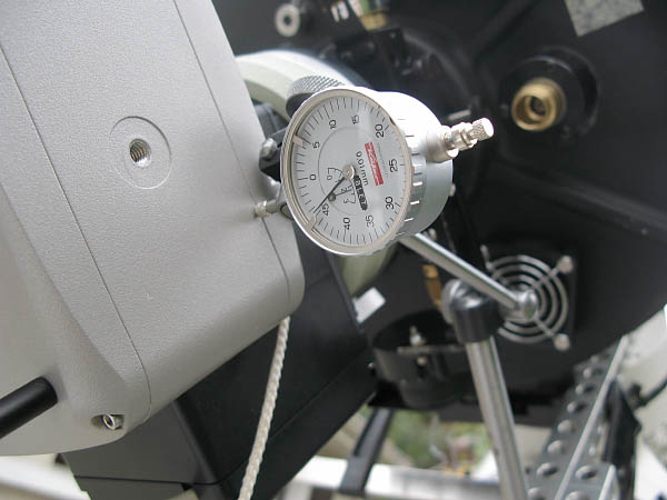
The C14 is tilted on both sides from the meridian with the same angle. A measure is done from two angles +/-45° (90° sum-total) and +/-90° (180°sum-total).
Subsequently, a second set of measurements is done on the main body of the focuser with the imaging train still installed. The contact point of the indicator is placed to the outer bearings level at 60mm from the rear cell of the C14.
The measures
The raw measures are the followings :
| total angle | CCD |
JMI |
| 90° (+/-45°) | 0,73 mm |
0,03 mm / 60 mm |
| 180° (+/90°) | 1,19 mm |
0,05 mm / 60 mm |
For a 90° rotation of the scope (i.e. 6 hours), the tilt is up to 0,73mm on the chip, i.e. ~80 pixels for 9µm² pixels.
The respectives flexures from the CCD are :
| total angle | drawtube flex. |
tilt due to the JMI |
| 90° | 0,63 mm |
0,1 mm |
| 180° | 1,02 mm |
0,17 mm |
The drawtube bend itself to an amount of 0,63mm dispite a strong tightening on the drive shaft with the lifting capacity adjustment knob. Moreover, the rear face of the focuser bend up to 0,1 mm with the 3"1/4 flange of the OTA.
So it's hardly surprising that on one hand the collimation changes throughout the night and that the flats cannot match the images on the other hand. The overall tilt should get worse with a possible miror flop on its own cell.
What could i do ? Retailing that poor focuser or trying to improve it ? I soon opted for the second option...
The new set-up
To totally remove the flexure, I chose to screw the camera/aol/caa neither in the drawtube but directly on the rear face of the main body of the focuser.
To achieve this, I have design an adapter which comes on the rear face with a set of eight screws. The rear face of the focuser was taped to receive the new part. My JMI is now truly unsealable...
The adapter include a dovetail shape allowing the assembly/desassembly of the heavy camera with three screws (120°).
Animation of the assembly :
What we see :
- The crayford and the new eight taped holes divided on the rear face. In the original drawtube, one can see an adapter with an internal m72 thread sticked in it. This thread is a Takahashi standard and allows the screwing of adapters with focal reducers.
- The new adapter centered on the external diameter of the focuser main body and fixed with eight mounting screws.
- A Takahashi Ocular 2" adapter screwed in the m72 I.D. of the drawtube.
- A focal reducer inserted in the previous Taka adapter (here, an AP CCDT67 reducer).
- The STL+AOL+CAA group mounted on the new adapter.
Lastly, the original 3,25" SCT back adapter supplied with the focuser would be machined to get a dovetail in the original slot on the 3,79" E.D. Thus the three locking screws will press on the flange of the dovetail to ensure an efficient flattening of the focuser on the C14 rear cell. This will trully eliminate the orginal tilt of 0,1mm.
Conclusion
From now on, the new dovetail adapter is permanently mounted on the JMI NGF-XTc. The straighness is greatly improved.
This new set-up make the focus by moving the CCD truly impossible. From now on, to make the focus, an optical device like a focul reducer sould be inserted in the drawtube. As i decided few months ago to work with a reducer, it is not a problem to leave in a such component !
The focus is roughly approched with the primary mirror knob. Then, an accurate focusing is done by moving the reducer on few motor steps. The drawtube should not have to bend under a such lightweight focuser (120g). By the way, the autofocus sequence with Focusmax should be made easier with the a such ridiculus weight to be move...