Construction of My Backyard Observatory
Jan Wisniewski, Harrowsmith, Ontario
Each type of observing has its own recquirements. One of the main and most intimidating characteristics of CCD imaging is the large number of different pieces of equipment connected to each other with a tangled web of cables. While CCD imaging could be done in a field, one quite quickly starts to desire a permanent observatory. That way everything can be kept ready for a clear night and observer saves himself/herself not only the time needed for a setup, polar alignement and disassembly, but also a chance of connecting wrong cables to wrong "boxes" (easy in a darkness while rushing to start observing) which may end that particular observing sesion prematurely (not to mention ruining at least a few following ones)!
My first backyard observatory was a simple 8 ft x 8 ft roll-off roof shed located in Sooke, BC. After moving to Ontario last March and finding a rural property North of Kingston, I have decided that the next one would be a bit bigger. Below I describe how that project developed...
Location.
By moving into farmland, I had avoided major light polution problems. Two closest towns of 500-700 people each are about 5 km to ENE and ESE, while light polluting Kingston is approximately 25 km to SSE. There are only two outside lights on neighbouring properties - one about 500m East and the other about 300m WSW. Have to convience neighbours to shield them, eventually.
Our house is located on the North side of the road and to avoid looking over the building when oberving the South part of the sky, I decided to build my observatory in NW corner of the property. Fortunately there is no obscuring trees in and around that area.
General plan
To have "reasonable" room inside, I have decided to build 8 ft. x 12 ft. roll-off roof structure with longer side oriented E-W. The roof will move toward East (some trees on E side of property block a bit of view in that direction). The pier will be located off centre - 4 feet from the W wall - so in the future there will be space to add another scope or a warm room.
July 20, 2000
Got a pile of lumber, plywood, OSB etc. delivered. Maybe 8x8 would have been a better choice ...
August 4, 2000
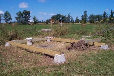
Finally started construction. Dug holes to bedrock (luckily just 1 ft below surface) to set up corners of the bulding as well as a larger hole for a pier. Filled them with stones and concrete, then set up patio blocks at the corners and checked that the floor frame would sit there square and leveled. Also set up plastic pail in the place of future pier and filled the hole around it with stones and concrete. Got that pail out before concrete set completely :-)
August 5-6, 2000
Set a 6 inch sonotube and 6 re-bars around it in the centre of a hole left by a pail. The plan is to have 10 inch outside diameter concrete pier with 6 inch hollow core to be filled with sand. Put some concrete at the bottom of the hole to keep sonotube and re-bars in place.
Then set up floor frame (2x6 presure treated lumber) with additional patio blocks located every 4 feet around perimeter. Everything was leveled carefully. The frame was then nailed in place and 2x4 cross-beams were attached inside it.
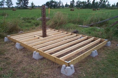
August 7-9, 2000
Floor was covered with 3/4 inch plywood. I used screws to attach it, so it will be easier to remove the floor in case I want to add another pier there in the future.
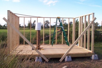
Then 6 ft high wall frames were build from 2x4s and nailed to the floor frame and each other. The plastic pail of top of the future pier had two functions:
1) protected sonotube from getting full of rainwater and desintegrating
2) prevented the builder from impalment in the case of fall from the ladder (remember re-bars around the sonotube?)
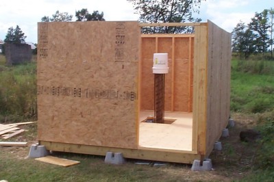
August 12, 2000
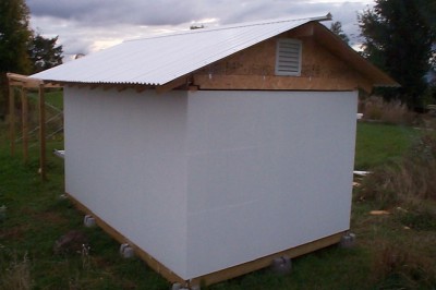
The walls were covered with OSB panels.
August 13-15, 2000
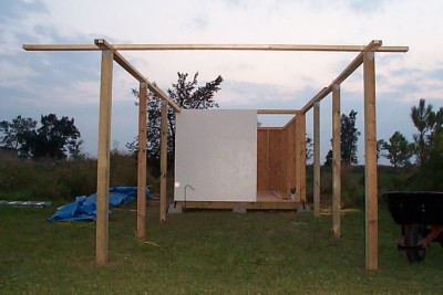
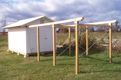
Walls were oil-painted and rails were attached to the building. In order to move future roof far enough, I have decided to have 16 ft long rails. Six 4x4 supports were set in compacted dirt (reaching down to a bedrock) and two 2x4 beams were nailed across their top to keep the spacing of rails fixed. Rails were then roughly leveled - they needed a bit of adjustement later on. While "under construction" view is shown below, finished rails were made out of two 2x4s nailed together with additional 1x2 attached to the top inside edge of them to creat a lip preventing roof from rolling to the side and crashing to the ground. A piece of 2x4 was nailed to the end of each rail for the same reason.
August 19-20, 2000
Two 2x4s with casters (5 each) were positioned on rails on top of the building and immobilized there with wooden blocks and long nails.
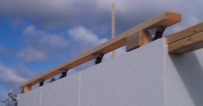
Then preassembled rafters (made out of 1x6s) were nailed to them with short spacers (cut of 2x4 lumber) in between so the rafters would not fold flat. Finally, 2x6 ridge was attached.
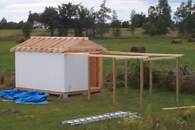
September 2-3, 2000
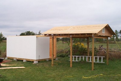
Roof and gables were covered with OSB panels and caulked. Also, vents were mounted into both gables. Then pulleys were attached to the roof and rails ends, so the roof can be moved with a rope. Similar pulleys were attached to the other end of the roof and to the Western wall so the roof could be closed. Also, eye-and-hook thumbnackles were attached to keep roof locked down when colsed.
With roof assembled, wooden blocks keeping it from moving were removed and roof was rolled back and forth along the rails to check the alignement. Two problems became evident and had to be fixed.
1) Rail supports were not stable enough and could sway to the side, potentially crushing under roof's weight. To prevent that instability, lenghts of metal chain were attached in X-shaped pattern (see one of the images below)
2) Rails were not level - shims had to be inserted between them and top of some supporting pillars so that all casters will be in contact with rails during roof's movement.
September 9-10, 2000
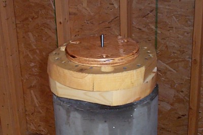
Now it was time to finish the pier. A desired section of 10 inch sonotube was slipped over re-bars. Then the spacing of upper ends of re-bars was adjusted and their ends were immobilized against internal (6 inch) sonotube with wooden blocks and duct tape (!). Both internal and external sonotubes were aligned vertically and immobilized in such orientation with strips of lumber attached to the inside walls of the shed. Then fast setting concrete was poured in between sonotubes and three carriage bolts were inserted into wet concrete (they will be used to attach telescope mounting plate later on).

September 16-October 1, 2000
Door was build and hanged. Then a plastic ridge and corrugated panels were mounted on the roof and caulked. Narrow piece of OSB was attached with hinges to the bottom of (shorter) Western roof gable - it will be lifted before roof is moved so the telescope will not be hit!
Then long plastic strips were attached to seal gaps below roof along rails as well as under gables. Finally roof gables and door were painted.
September 23-24, 2000
Even before the exterior was finished, I started to put equipment inside.
After sonotubes were peeled away, the opening in the floor was covered with plywood, leaving only about 1 cm around the pier. Center of the pier was then filled with fine sand to help dampen any vibrations.
Then two large floor vents were mounted into the floor to help to keep inside temperature close to that outside.
Telescope mounting plate (made of nailed together two circular pieces of 2 inch thick lumber and a smaller piece of plywood cut to fit depression on the botton of Celestron SCT wedge) was I bolted to the pier. Additional long bolt was run through the center of that adapter plate - then on a clear night the wedge alone was centered over it and oriented toward Polaris by eyeballing!
Then the wedge was attached in that orientation with long screws and the telescope was mounted. Preliminary polar alignement was done through to finderscope and then refined by two star drift method using CCD camera.
Observatory started to be operational on the night of September 24, 2000.
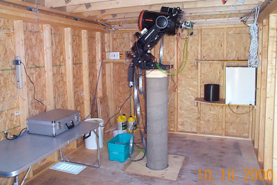
All the pieces of equipment were arranged inside as conveniently as possible. Telescope drive and dew heaters are powered from 12V deep cycle battery (in a green box). Cookbook 245 CCD camera is attached to the telescope through filter wheel and focal reducer. It is powered from power supply (sitting on the shelf in the far corner beyond the scope) and cooled with fluid circulated by 120V submersible pump (inside white bucket). Camping table is useful to spread maps and when changing imaging accesories (like filters inside the filter wheel). The bottom shelf in the right far corner accomodates dew shield and light box (for taking flat field images) while the upper one is used for a laptop.
A few additional modifications are needed in a near future. Warm room gets quite urgent with winter approaching. Also, guide scope assembly has to be rebuild and attached to the scope as well as warm cabinet has to be build to house 386 computer controlling autoguider (Cookbook 211) CCD camera.
Later Improvements:
December 2001
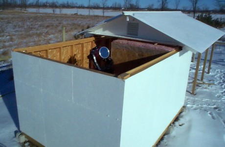
Winter is a lot colder in Ontario! Had to build warm room using OSB panels and a lot of pink insulation. All electronics (including telescope's drive controller) were moved inside and kept warm inside smaller cabinets with electric heating pad. Large electric heater is used to warm up the whole warm room when observing.
Spring 2002
Trap door was cut out in warm room's wall and openning (inside small door) covered with plexiglass. Guiding computer was turned around in its cabinet and keyboard mounted outside. That way screen can be observed and computer controlled during the search of guide star!
Summer 2002
To facilitate cooling, 25 ft. long section of copper tubing was spliced into plastic tubing between pump and camera head. Copper tubing was bend into large coils and hanged on the inside wall of the observatory.
Number of visitors:
©Jan Wisniewski