|
|
|
The design and building of a large dish antenna rotor
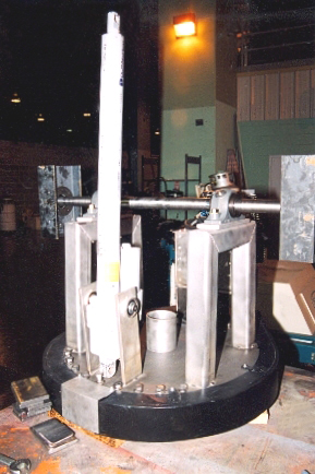
Text and pictures by Cliff Bates, KC7PPM Other concerns (III) To move the dish vertically presented a major problem(s). To simplify things I decided to use a motor operated screw drive ram. The choice of a screw drive was based on the fact that it was simple, rugged, powerful, and very low maintenance. Plus it could be designed to reduce the strain on the dish support arms by applying the dishes lifting and lowering forces at a point directly behind the dish, rather than through the dish support arms. This created a 3 point support system for the dish, rather than the 2 point system using just the dish support arms. It also made the dish much more stable and resistant to the wind and other forces acting on the it. In designing a rotor system there is a tendency to focus all the design considerations on the weight of the dish and forget about the relatively light objects to be hung way out beyond the dishes surface. For example the horn and other equipment at the dishes focus. Obviously in comparison to the weight of other major items, the microwave horn, wave guides, and preamps seem like nothing. However they have a surprising effect on the rotor performance because of the distance of this equipment from the dishes pivot point on the rotor bearings. These little items can exert a surprising amount of leverage, not only from their weight hung way out there, but also from their inertia forces when being started or stopped. For example a weight of 1 lb. at a distance of 1 ft. = 1 foot pound. The dish focus on my dish was located 11 ft. (3.3 m) from the rotors bearing supports. The horn I used was a very good one, almost 2 feet (60 cm) long, and had a scalar almost 16 inches (40 cm) in diameter. Added to this was the weight of the preamp, a junction box, TV camera, waveguide, power cabling, mounting ring, and transmit/receive switching relays. I ended up with 22 lbs. (10 kg) of equipment hanging out in space beyond the focal point. This translates into a minimum of 222 ft/lbs. (147 m/ kg) of leverage alone, excluding any inertia forces generated when the dish was moved up or down, or horizontally! To handle moving the dish vertically I used a ram that exerted 1600 lbs. (725 kg) of force, using 115 VAC., and having a 36 inch (91 cm) stroke. 1600 lbs (725 kg) of lifting force may sound excessive, but it was not. It allowed for the weight of the dish, the dish support structure, and any wind acting on the dish while it was being moved. It also held the dish in position during windy conditions with the same amount of force. Normally the dish and support arms are balanced with counter-weights of equal weight so the elevation drive system is lightly loaded. During movement of the dish the drive system it is only overcoming any weather effects on the dish. However when the dish and rotor are being assembled, the dish will have to be moved to attach the counter weights. To do this the ram, (or any other type of lifting mechanism), “must be able to move the entire weight of the dish, or its counter weights, and its support structure, unbalanced”! The only problem I had with the screw drive setup was that it was slightly to fast in controlling the dishes up and down movement. This made fine elevation adjustments sometimes difficult. It was not the fault of the screw drive, but my fault in ordering the wrong drive speed.Sometimes slower is better, especially when only driving through a 90° arc. No matter what means are used to elevate the dish, I would “strongly” suggest that it lock in position when the movement stops. Or power is removed, so the dish will not move when the dish isn’t being used, or during a power failure. Do not rely on applying a manual stop or brake!
Also I would recommend a couple of other features be included. In the event either drive motor failed, I wanted to be able to move the dish manually. Consequently I had an option included in the ram of being able to operate it manually if necessary. This was anything but convenient to do with a wrench, but it allows a last resort to get the dish and your investment out of trouble when nothing else works. (The AZ rotor worm gear box also had a wrench option.) Another must, is a “reliable” over travel limit cutout. In the case of screw drives it is possible to unscrew the ram out the end of the support tube if there is no limiting device to stop its extension. Needless to say, it is not good for the shape of the dish if it is dropped down into the support post because the elevation operator ram over extended and drop out. More than once the elevation cutout saved my dish because I had become to focused on following the source I was tracking, than on the dishes position. This same logic applies to azimuth rotor limit movements. There is nothing like shearing off the wave guide and/or power cables because you hit the wrong direction button accidentally. Or you weren’t paying attention to the dishes position and started the dish around a second time...! Of course using a screw drive ram isn’t the only way to move the dish up and down. Looking at what others have come up with for moving their dishes on some of the web sites shows what can be done. Especially when driven by the need to accomplish something. Several of the designs I found were powered by hydraulics.In my case I liked the idea very much, but because of the heat and cold where I live, I felt it would cause to many problems. Some of the aspects of using hydraulic systems were very attractive.Such as almost unlimited ram power, and the cost of hydraulic rams are considerably cheaper than electric screw drives. But hydraulic systems required a pump and motor, an oil reservoir, and the associated plumbing. Also an interface is needed for the dish position control circuit to change the electrical signals into hydraulic movement. That was beyond my monetary means. I decided in my case it would be cheaper and easier to use a electric screw drive ram. However your experience, needs, and luck in finding something else to do the job could lead down a whole different path. The cost of a new 36” (91 cm) electric screw drive ram, with a manual emergency operator, a ram travel position limiter, and position locking brake, was $1800. I wouldn’t recommend buying these USED unless you really know what you were doing. A lot is riding on it. The support shaft
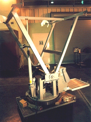
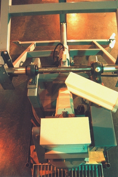
To support the dish an “A” frame design was used, with the large end legs attaching to the dish mounting ring with eight 3/8th” bolts. The support arms were 2”x 4”x 1/8th” wall rectangular steel tubing. Each leg, of each “A” frame was cross tied to the other with the same stock as extra stiffening, and to dampen any side to side forces acting on the dish. The lower cross tie was cut and rewelded to allow the screw drive shaft to pass through without interference. To support the dish, its supports, and a equal amount of weight in counterweights, a 2” diameter stainless steel shaft was used, (to eliminate rusting) riding at each end of the shaft in two 2” tapered roller pillow block bearings. Each bearing was rated for a 2 tons of rotating load. To attach the dish support shaft to each of the dish and counter weight arms, a 6” “I” beam, 12”long was used as a mating surface between the two opposite support arms of the counter weights and the dish, and bolted together with sixteen 5/16th” bolts. The center of the 6” “I” beam was bored out to receive a 2” collet shaft coupling.This was then bolted to the “I” beam with 6 high tensile strength bolts that came with it. This method of attachment allowed the “I” beam to be slipped on the shaft and aligned with the support arms from the dish, without having to be concerned with aligning key ways, or pinning the shaft. Once the shaft coupling was aligned to the support arms, the coupling bolts were tightened down. This cinched the coupling collet down on the shaft with atremendous locking force, without weakening the strength of the shaft with key ways, or holes for pins. This design also had the advantage of being “relatively” easy to remove without scoring the shaft if I needed to. However, if in your design the lifting torque for the dish arms is applied through the support shaft, key ways will be needed to prevent slippage. The torque required will be to high to rely on friction alone between the shaft and the coupling to do the job. The support shaft was kept aligned between the two pillow block bearings with two shaft keepers on either side of each pillow block bearing. These were held in place with 2 large setscrews per keeper. These seated into a small dimple hole drilled in the shaft after everything was aligned.
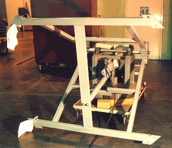
To connect the support structure to the upper rotor mounting plate, two bearing support structures were cut and welded into an inverted “U” out of 2”x 2” heavy walled square tubing. The legs of each “U” were welded to the rotor mounting plate, then two ½” holes were drilled in cross piece of each of the “U’s” for mounting of the shaft bearing pillow blocks with high tensile strength bolts. As an after thought, the two “U” supports were cross tied under the shaft with another piece of tubing to prevent any side-to-side forces on the supports from being transferred into the dish support shaft. This is a good idea when dealing with a lot of rotating inertia. The counterweight arms were made of the same stock as the dish supports. Two cross braced arms each carried a 450 lb. (204 kg) piece of 10” (25 cm) diameter shafting cut from a small scrapped out hydro generator shaft. The length of each counterweight support arm was the same length as the dish arms.Each counterweight support arm weighed 50 lbs. (22.6 kg) without the counterweight attached. The counterweight arms had two minor design flaws, both of which didn’t show up until the project was completed. The total weight of the counterweights and arms added up to the same weight as the dish, 850 lbs. (385 kg), but I had forgotten to allow for the weight of the equipment at the focal point. The horn supports, and quite a bit of cabling and waveguides running from the pivot point of the dish support shaft out to the focal point. Surprisingly I had to add another 200 lbs. (90 kg) of bagged lead shot to the counterweights to overcome the leverage, and balance everything out. It wouldn’t appear that a 200 lbs. (90 kg) of unbalance load would be noticeable, but it is when a ton of equipment is mounted up on a 17’ (5.1 m) pole. Small deflections become evident in the setup as the dish changes position from vertical, where all loading is straight down the support pole, and horizontal, where the imbalance due to that leverage we discussed earlier, shows up and wants to topple that balanced ton off the top of the pole. The deflection of the support pole was hardly detectable, and was a lot less than normal wind loading. But it was enough to let you know things were not quite as they should be. The second flaw to showed up was I didn’t cross tie the two counterweight arms together. This was because the counterweight arms went on either side of the support pole when the dish was in the vertically stored position. This problem didn’t show up when the dish was moved up or down. However when the dish was rotated around, even at 1 RPM and came to a stop, the momentum of 1000 lbs of counterweights deflected the counterweight support arms from side to side about 2”. Again, it was nothing serious, but it was just one of those things that needs to be improved upon. I had included a local control station at the bottom of the support pole, besides the main control point in the shack. When rotating the antenna from down at the base of the pole, and the counterweights passing overhead, there was cause for one to contemplate how well the counterweight arm welded joints were handling the slight side to side swinging stress. If I had it to do over I would have cross tied the arms together with a bowed cross piece that passed around the support pole. In comparison, the dish, due to its supports cross bracing, was as solid as a rock. The positioning system For controlling the dish movement and position I looked into several methods, and ended up with probably the simplest. Though the design was not the best for accurate positioning, it was reliable, and used a minimum of hardware. It was also very low maintenance, and allowed for future improvement using the existing cabling. Designing electrical circuits is not my cup of tea.I’d rather vacuum the house, or pull weeds. And I’m not very fond of doing either of those. Which has always made me wonder why I ever got interested in RA and amateur radio. Probably two of the longest running hobbies I’ve ever enjoyed. I wanted a positioning system that would take advantage of the rotors power and positioningcapabilities. To do that I took a very serious look at using encoders for rotor position feedback. Unfortunately, at the time I had to down grade. To setup of an encoder system was to complicated, especially combined with an automated computer control for tracking. This of course is the way to go, but beyond my circuit skills, and budget at the time. Many of you will have no problem in this area, but I have this genetic defect when it comes to it. Until I could not only afford, but could come up with a encoder system, I decided to use TV camera’s looking at large degree wheels positioned on the rotor. Today’s small TV camera’s are relatively inexpensive, very reliable, rugged, and have very good resolution for the cost. To get the desired position pointing capability I bought two of the biggest protractors I could find at the drafting supply store. To sharpen the focus, and thus the position accuracy, I bought two Macro lenses for the azimuth and vertical position TV camera’s. These lenses worked great, and moved the pointing accuracy of the rotor into the dishes beam width capability. A weather proof third camera was mounted on the end of the antenna horn looking out toward the antennas beam width. All the camera’s were low lux, auto iris, B&W camera’s, with 420 lines of resolution. These camera’s fed into a multiplexer, so I could display all three images on one 21” (53 cm) B&W TV screen. To control the rotor motors, each of which were 115 VAC, I decided if I was going to have to do the positioning manually, I would keep it simple, and use push button switches. These were not Radio Shack push buttons, but industrial grade control push button switches that could handle the motors starting current. The switches only operated the motors when they were depressed, thereby giving fine positioning control. They worked fine, eliminated relays, and never welded a contactor. I used 8 of them, between the two control stations, for up, down, clock, and counter-clockwise rotor movement. Although the positioning system worked great, and never caused any problems, it was labor intensive. More so than I thought when I was building it. The main problem, disregarding the almost constant adjusting for the earths rotation, was caused by the dishes beam width. As the dish size becomes larger, or the frequency is increased, the beam width of the dish becomes smaller, and the sensitivity and resolution increases. BUT, the rate of adjustments needed to keep the dish beam width on the source increases proportionally also.Until a manually adjusted system becomes impractical. I would say a 16 foot dish approaches that limit. Though my TV setup worked fine for drift scanning, it left a lot to be desired when it came to tracking a source. It should be kept in mind, that “across the antenna’s beam width” is a bell curve of sensitivity, and the center portion of the hump of that curve is the goal of the tracking device. Otherwise your losing the reason for having a larger antenna if you can’t track to the dish’s full maximum beam sensitivity capabilities. Today it is possible, and will be well worth it. Bottom line
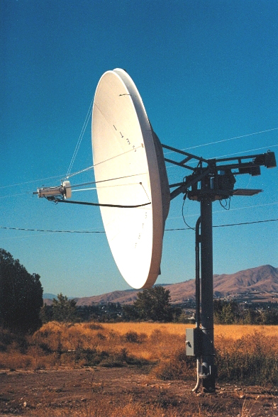
When I started the project I fully expected to have it up and running in 6 months. Actually it took a year and a half. Even then I had some employment equipment advantages that some of you may not have. For example I used the work shop where I worked to do most of the work. I have a pretty good shop at home, but I needed more space. Plus when your moving some of the weights we’ve been talking about here, a big hoist is a must. Also a place to attach the hoist that won’t bringing the roof down helps keeps peace in the family. This is not to say you can’t build your own dish if you don’t have these things. WHERE THERE IS A WILL, THERE IS A WAY. If your will to build one is strong enough, and want one bad enough, you will do it. As I said, look on the Web at all the other amateur dishes. Then keep in mind that Noah built the Ark without a power saw! If you can believe that! And historians are still trying to figure out how the Egyptians ever moved all those blocks of rock around to build the Pyramids. However it is a shame the Egyptians were not into parabolic dishes back then. I would gladly have included some prints and drawings of the rotors design in this paper, but there isn’t any. Just these photographs.The project came together as the pieces appeared, and as the problems were solved. Ideally I should have made drawings, bought the needed items, and built it. Normally I do that. However on this project I started with a dish and a thrust bearing, and things were just adapted to fill in the need between the two. I don’t believe this is necessarily a bad way to go, at least for building this kind of project, where your adapting things available to meet the need. Suggestions 1. First get, or build the dish. Or know the size and the exact weight of the dish your going to use. Figure wind loading, etc. 2. Get the thrust bearing. This is the key piece, “it makes or breaks the entire project,” literally! Mine is called a slew bearing.They come in all different sizes. 3. Cranes are expensive, so over design everything for reliability that will need a crane to service, or repair. Besides, Mother Nature will do her best to try and tear down everything. 4. Always look ahead on the project. I have mentioned some examples of where I blinked. 5. Build your dish where it will never have to be moved during its lifetime. It is kind of like planting a tree. Once located, it is a real problem to move. Especially with a 35,000 lb. (~16 ton) block of concrete attached to the end of it. The number 5 suggestion on antenna placement is interesting. You might have noticed that this large dish project is often referred to in this paper inthe “passed tense.” Actually the day before the dish installation was completed I was notified that the property I had put it up on was going to be sold. The apple market had gone in the bucket, and the profits off the apple crop would not even pay the property taxes on the orchard, and the spraying. However I was told that it would probably be 2 or 3 years before the property actually did sell because it was river front acreage, and consequently it was very expensively priced. To everyone’s surprise the property sold in 3 months. The new owner was nice enough to gave me till the following spring to remove the antenna. I have not put it back up, and it has been stored in a shipping container for the last 6 years. It awaits a computer tracking setup. To pinging off the Moon Building a large dish antenna is not only a challenge, but there is a lot of fun and self satisfaction in doing it. Much to my total surprise, the neighbors around the area actually loved it! It was something different, that people found interesting, and were very curious about it. To read : Hams in the Sky
Several times if the Moon was up, I would turn on the transmitter, and let them listen to a ping off the Moon. You could see for the first time in their lives, they could suddenly relate to the speed of light. As they looked at the far off Moon, and I pressed the transmitter key, they then heard the ping returning 2.5 seconds later. The same wonder applied if they were just listening to the sounds of the stars, or the Sun for that matter. If the Moon, or stars were not up. It was interesting for me to watch their faces change to an expression of fascination, and yet know, I was seeing a reflection of myself in them. Letting them experience what RA was all about, also apparently had an unexpected side benefit in that there was never any vandalism done to the antenna. I had fully expected some, setting out there in a field all by itself. I would find footprints, bicycle, and motorcycle tracks in the dirt around it, but there was never any painting, shooting, or attempts to climb it. The neighborhood around the area watched out for it, because they liked it. It was also used as a direction finder to their houses, and was quite the conversation piece of guests visiting them. Even the dishes picturemade the front page of the local small town newspaper. If I were to build another one, I don’t think I would change much of anything except for the items I mentioned that needed to be improved. It was a good, strong design, that worked very well. Give one a try. I warmly thanks Cliff Bates, KC7PPM, for having shared his experinence with us. For more information - Dish antennas (on this site) EME installations built by amateurs : - F2TU (8 m dish) - G4CCH (5.4 m dish) - W0LMD (4.2 m dish).
|
||||||||||||||||||||||||||||||||||||||||