|
|
|
Technical review
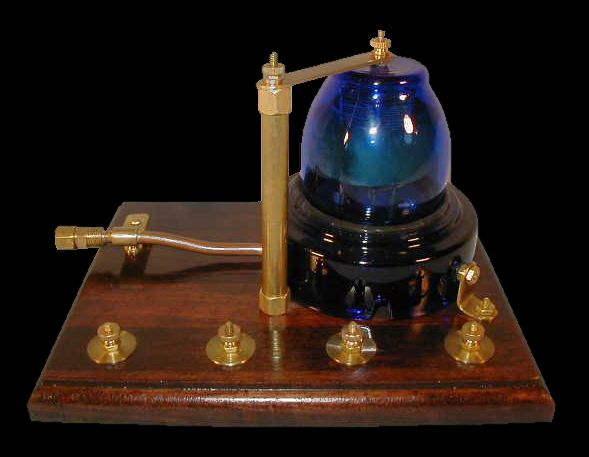
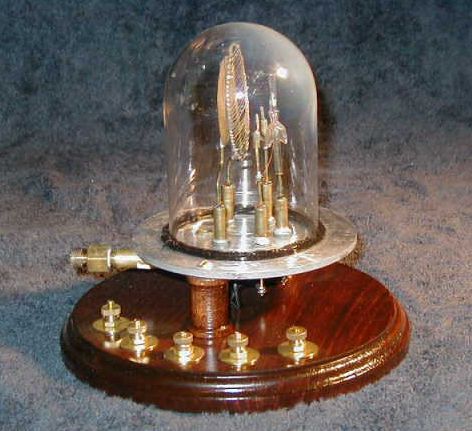
Principles of amplification (I) There are two main fields in which amateurs use amplification : in Hi-Fi systems and in amateur radio. Using a knob or a cursor, from a very weak signal extracted from a CD reader or a tuner you can easily generate a deafening sound. Your signal has been amplified. But how all that work, specially on the theoretical level ? I think that it is wiser before using a linear amplifier to get a good theoretical and practical knowledge on this very special accessory. That can avoid you making mistakes in using its controls or working on the air. We will review the theoretical aspect hereunder replacing its invention in its historical context. To be complete its practical aspects will be discussed on two other pages in which we will see how work a tube and a solid-state HF amplifier. Once all this memorized, one can say that you will be almost a pro of amps, HI ! Let's see first the characteristics of the vaccum tube, the first and the simplest component used in our grand-parent radios to amplify signals. The short history of the electronic tube In 1883, Thomas Edison discovered the electron emission in manipulating vacuum tubes, an effect that will be explained by O.W.Richardson in 1901. An electronic tube is consisting of a electronic circuit placed in a vacuum chambre or in an ionized low pressure gas enveloppe (gas tube) made of glass or metal/ceramic. This small circuit controls the flow of electrons transiting between two or more electrodes, from the negative pole to the positive one. In its simplest version, the diode, the main tube electrodes are the cathode (negative) and the anode (positive), also name the plate. How does it work ? To free electrons from the surface of an electrode made of brass in the first years, now made of carbon or silicum, the cathode has to be heat, directly through the electrode or indirectly (usually) using a small filament placed very near it in the bulb and linked to two external connectors. In 1904, the Englishman J.A. Fleming developed the first vacuum diode using a cathode and an anode, known as the the Fleming Valve. In 1908 he invented the tungsten filament. View from below, this diode shows a socket with four connexions. When we close the circuit and heat the cathode, the filament lights like a bulb and radiates its heat to the near cathode. Its surface emits a cloud of electrons that are attracted by the positive anode, generating a current of about one volt or less in the tube, this is the thermo-ionic current. If the cathode is negative the current moves in one direction and is blocked in the other one.
The more the heat is high the more the current is intensive. Usually the voltage applied to the filament is ranging from 6.3 to 12.6V. To get a control on the ouput current without modifiying the input voltage, in 1906 Lee De Forest added a plate control to the first detectors tubes. Four years later R.von Lieben inserted a third electrode, named the grid, in the vacuum tube, creating the first triode. Lee de Forest improved this invention using a positive feedback in 1913 and quickly after AT&T developped the first vacuum tube repeaters for its new telephony network.
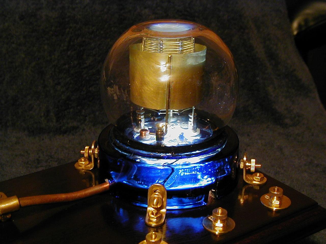
What is the role of the grid ? The electric field created between two elements is directly proportional to the potential difference between them, and indirectly proportional to the distance between them. That means that if there is a small potential difference across the control grid it can created a much higher field than the same potential across the plate. Practically the electrons at the cathode are pushed or pulled by the field from the control grid and not the plate. They are not influenced by the plate until they get passed the control grid. Since the potential difference is a state function, the grid will not affect the final point of the electrons sticking to the plate, but only the number leaving the plate. That way, by applying a signal to the grid, you can control how many electrons leave the plate, and then the final voltage output since it is directly proportional to the number of electrons passing through, better known as the current. Again, the current is directly proportional to the potential difference, and the potential difference is indirectly proportional to the distance between the elements, so the alternating potential at the control grid produces an alternating potential at opposite direction and much greater magnitude at the plate. The grid was originally made of a corkscrew wire or of a fine wire mesh placed between the cathode and anode. In applying a fluctuating voltage to the grid, negatively polarized against the cathode (like is a FET transistor), a large fluctuation in the current was observed between the cathode and the anode. This triode acted as a signal amplifier, producing to the output signals up to 20 times greater than the input signal. This grid plays also the role of a regulator and can slow down the electron flow circulating in the tube, hence in name of "control grid". Grids used in large power tubes having to sustain much heat (over 225°C), they are often made of tungsten or molybdenum wire welded into a basket form. Some large power tubes like tetrodes use basket-shaped grids made of graphite.
But the triode had some drawbacks, specially its grid-plate capacitance, the so-called Miller effect. This effect allows a small quantity of the output signal to be reinjected to the grid, transforming any good amplifier in oscillating circuit. In 1919 A.W. Hull inserted a screen grid between electrodes to suppress this unsollicited capacity. To get greater amplification, additional grids were added to these tubes, between the control grid and the plate. Tetrodes come with 2 grids, the 2d being called the "screen" grid because it screens, or isolate, the control grid from the plate. Tetrodes produce output signals about 600 times greater than input, and pentodes, constituted of 3 grids, amplify the signal about 1500 times. Pentodes can produce a secundary emission. Electrons striking the plate can be reemitted or induce a new emission. To thwart this effect in 1912 G.Leithäuser inserted a third electrode named the suppressor grid, that thanks to its negative polarity collect the stray secondary-emission electrons that bounce off the plate and sends them back to the plate, eliminating the "tetrode kink".
At last, electronians discovered that if the velocity of the electrons flow was very high, these last can strike the anode in producing X rays; this was the invention of cathode ray tube (CRT). In this device, the electron beam can be directed on to a phosphor screen to produce a picture on a oscilloscope, a video display or a TV screen. In a tube, the flow of electrons moves from the plate to the cathode by electrostatic attraction. This is thanks to the voltage change applied on grid(s) that the amplification factor is controled. Unlike semiconductors (excepting FETs), the movement of a very low mass of electrons within the active region of the tube has for consequence to quickly change currents. When manufacturing such tubes, there is no limit to the current density in the space, and the electrodes which do dissipate power are usually metal and can be cooled with forced air, water, or other refrigerants. With these improvements today's tubes are become active components and constitute a device of choice when signals have to be amplified to power levels of more than about 500 watts. To Check : Frank's Electron Tube Data Sheets Tubes characteristics Having understood how work physically a vaccum tube, let's see its characteristics curves and how the input signal is amplified on the anode.
Take a cheap triode supporting 300V nominal on the plate. Invert your battery polarity, placing the positive pole to the ground. Insert a voltmeter between the grid and cathode completed with a cursor switch and an ampere-meter inserted between the battery and the anode as displayed in the schematic at right. This circuit will allow us to see that the grid voltage can fluctuate between -35V and 0V what will generate current. With the miniampere-meter you can measure the current yield by the tube. While the voltage is -35V the anode current is 0 mA because electrons cannot pass through the very negative grid potential. This position is the cutt-off point where the tube is blocked.
When the grid voltage is very near the cathode potential (about -2.5V) some electrons from the cathode begin to be attracted by the anode, passing through the openwork grid; at that moment you can read an anodic current of a a few amperes. If you continue to increase the grid voltage, the current at the anode will reach its maximum, say 35 mA then it will be saturated. This effect reminds the behaviour of the FET transistor. If you increase the plate voltage, for the same polarisation value (between grid-cathode) the anode voltage will increase too. However you cannot indefinitely increase the plate voltage because you will explofe your tube. The screen grid will drain too much current, substituing to the (non-powered) plate what will lead to its destruction. Therefore, on power amplifiers manufacturers have inserted a security circuit to avoid the tube destruction in case of malfunction or bad manipulation. When the plate voltage disappears for one or another reason, the tube does not function. Excellent thing for the novice electronician playing with his active components ! Based on this experience, fix the load resistance to 50 kW and the grid voltage to -5V. At rest (powered but without signal) the tube drains 2 mA, so a voltage of 100V (U=RI). At the anode-resistance junction our voltmeter reads a voltage of 300-100 = 200V what represents a power consumed by the resistance of 0.2 watts (P=RI2 or P=UI).
Apply an alternative signal to the grid which excursion is 4V. Knowing that at the operation point the voltage at rest is -5V, in this case the grid voltage varies from -7V to -3V. Do some measurements. For a grid voltage of -7V the plate current is 1.35 mA. It is 2.65mA at -3V. The voltage drop in the plate resistance (between the ground and anode) is respectively [300 - (U=RI)], so 232.5V at -7V and 167.5V at -3V. This short experience shows that a small signal amplitude applied at the entry (4V peak to peak) produced 65V (232.5-167.5) on the anode; the signal has well been amplified over 16 times. This is the amplification factor m. It is defined as the ratio between variations of the anode voltage and the variations of the grid voltage.
In best cases, using linear amplifiers, the output signal fit the input one with a higher excursion (amplitude). If the input signal voltage is too strong, a bias will be introduced at the grid that will begin to produce current, saturating the tube and generating distorsions at the output. In audio applications, a too low amplification can also distort audio signals and will generate many harmonics that can distroy high-pitched speakers. But there is a second effect. Any increasing of the input signal reduces the ouput voltage, and the signal phase is shifted of 180°.
Next chapter |
||||||||||||||||||||||||||||||||||||||||||||
|
|
|||||||||||||||||||||||||||||||||||||||||||||