|
Technical review
How
to select a solid-state HF amplifier ? (I)
If
you like digital gears and if complain about performances of your antenna
system, in this case the purchase of a solid-state HF amplifier can be a good
solution to work DX stations in better conditions.
I
do no mean that your amplifier might replace a defective antenna.
Far from me this idea. Do never use a high power to compense the
poor performances of an antenna because it does not work. This is indeed
the best way to create QRM or dissipate more heat !
If
fundamentally a solid-state amplifier ensures the same
functionalities as a tube amplifier, its architecture is quite
different as well as the intensity of voltages and currents flowing
in its circuits.
Tube
and a solid-state amplifier : differences
Not
only currents and voltages are differents in a tube and a
solid-state amplifier but the load resistance differs also in both
designs. So if a tube amplifier requires a RF tank circuit (Pi-L
network) to transform the load resistance in 50-ohm, due to the low
load resistance of a solid-state PA module, a broadband architecture
is requested using ferrite-core transformers. As
the input-transformer primary presents a 50-ohm resistive load,
tuned input networks are no more necessary because the exciter
always sees a 50 ohm resistive input; on other words, an auto-tuner
is not required to drive a solid-state amplifier.
To
get 1 kW PEP output, you need first twice that power in DC input
(see below), then several pairs of RF power devices, usually
MRF-150 MOSFET power transistors, each of them being a larger version
of the PA stage that we find usually in HF transceivers. If a
tube amplifier uses only one PA module, the tube(s), a solid-state
amplifier is always push-pull to reduce even harmonics (due to low Q).
In
a kW-class amplifier we find an hybrid-transformer power-splitter.
The splitter and combiner can for example be 5-ports circuits, 1
input and 4 outputs, the combiner having 4 inputs and 1 output.
Contrarily
to the tube amplifier, in which a tuned circuit like a Pi-L network
helps reducing harmonics, a solid-state amplifier uses low-pass
filters (LPF) behind the combiner output to remove harmonics
and spurious emissions to a level less than –46 dBc (up to -60 dBc).
Its output is routed via the output T/R relay to a
reflectometer for security purposes, and then to the antenna
connector. This last entry is wired via the input T/R relay to the input port
of the splitter. All this building makes a broadband, self-tuning
solid-state HF amplifier.
For
short, a solid-state amplifier is constituing of the following modules :
a PA stage, a controller board, an ALC, low-pass filters, an optional
(automatic) antenna tuner, a band-switcher, input interfaces, and
the power supply unit. Let's review each of these modules.
|
Characteristic |
Tube
amplifier |
Solid-state
amplifier |
|
PA
module :
RF
power devices :
RF
power voltage :
RF
power currents :
Load
resistance :
Matching
network :
RF
input circuit :
Match
to 50-ohm load : |
Tube(s)
1
to 4 tubes
High
(4 kV)
Moderate
2000
ohms on anode
Q
= 12
Broadband
or broadly-tuned
Pi-network |
Transistors
4
or 8 pairs of RF power transitors
Low
(50 V)
High
(40 A)
3
ohms on collector
Q
≤ 1
Broadband
Ferrite-core
transformers |
|
PA
stage
Linearity
and efficiency
As
explained in pages dealing with amplification
classes, the main limiting factor of power devices is the constancy of power gain over the entire
power-output excursion. Generally, MOSFET transistors will exhibit superior linearity as compared to
older bipolar junction transistors (BJTs).
|
|
|
Linearity vs.
temperature. |
Due to the
higher voltage excursion, amplifiers powered between 40-50V DC (thus
desktop models like Yaesu VL-1000
Quadra) exhibit also considerably better linearity, and thus lower
IMD, than units powered on 13.8V DC, usually portable, because the
longest is the output/drive power curve, the better is the linear portion.
In addition, it is more difficult to design a power supply for a 13.8V
amplifier due to high current requirements (e.g. typically 80A peak for a
500W PEP amplifier like Ameritron
ALS-500MX). So usually a tube amplifier is more linear than any solid-state model.
At
last the power output is determined by the maximum ratings of
RF power transistors, and by the linearity of these devices. Usually
these latter are arranged in push-pull pairs, each module being
able to sustain 150W or 250W output.
Due
to these specifications, you will find 4
push-pull pairs of 150W power transistors in the Yaesu VL-1000
Quadra or Tokyo Hy-Power HL-2KFX amplifier to get 1.2 kW PEP output
(for 2.1 kW DC input).
Power
gain
The
power gain of a RF transistor, defined as the ratio of RF output
to RF drive power, decreases as frequency
increases, MOSFETs offering a power gain a bit higher than BJTs (at
14 MHz, respectively 12 dB vs 10 dB). That means that to drive a 1
kW amplifier, BJT's requests input power levels of 100W against 65W
only using MOSFETs. If the second model is more efficient, in all
cases any solid-state transceiver will drive a kW-class amplifier to full
rated power.
Cooling
system
A
solid-state class AB amplifier yields an efficiency of 45-50%. In a
model rated at 1200 W PEP there are only 600 W output, the
"missing" watts being transformed in heat (like a car engine).
Due to the high power of RF devices, in emission this heat is dissipated
in the amplifier case. Therefore a quality PA stage requires a very efficient
cooling system, able to maintain the case at nominal temperature.
To
respect good RF practices and to prevent an automatic shutdown of the amplifier, the PA cooling system
must maintain the amplifier case at nominal temperature, around 80°C (176°F) for at
least 30 min in SSB or 10 minutes in key-down CW transmission at
rated output. This is accomplished using a heatsink or a heat-dissipator system,
both blowing forced-air to maintain transistors at low temperature.
In a tube amplifier the heat generated by tubes is simply dissipated
in the air and blow out by a fan.
If you mainly use your amplifier for contests and
hunting DX stations, or at high ambient temperatures (tropical climate) you might need a more
powerful air circulation, able to dissipate much more heat. In this purpose, some manufacturers
like Yaesu specify the power-output rating as
ICAS, what can mislead to de-rating the duty cycle of power transistors.
|
CCS
vs ICAS;
Continuous
Commercial Service (CCS) covers applications
involving continuous operation in which maximum
dependability and long life are the primary considerations.
Intermittent
Commercial and Amateur Service (ICAS)
is defined as a service including the many applications
where the transmitter design factors of minimum size, light
weight and considerably increased power output are more
important than long tube life. In this service, life
expectancy may be one-half that obtained in Continuous
Commercial Service. |
However
we should all known that above the "maximum ratings", it
usually result in catastrophic failure. Therefore power devices
running all the time should refer to the more conservative CCS
ratings. In the same way amateurs should never force the power stage
of their amplifier too high to preserve its lifetime. Keep in
mind and we will repeat it again, that the nominal power of your
transceiver (usually 60-80W) is far enough to drive your amplifier
at the rated power without over-heating the system.
|
|
|
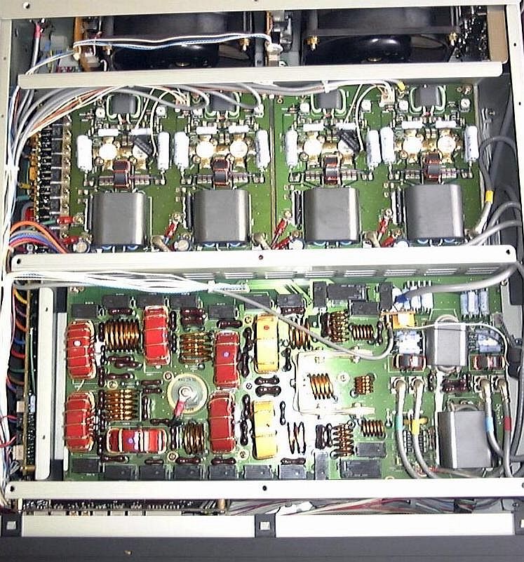
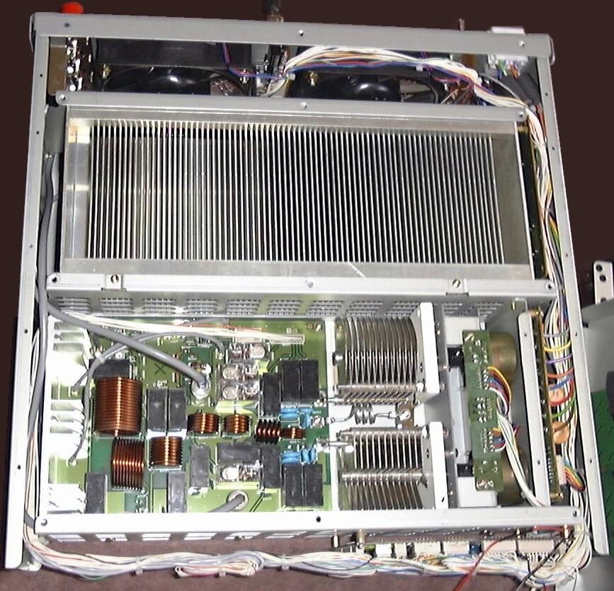
Inside
this Yaesu VL-1000 Quadra
amplifier we discover in front of the fans the large heatsink
that preserves the case to exceed a temperature of 80°C
(176°F) nominal.
|
Cooling
systems are various, all depending of the amount of heat to
dissipate, the technology used and the space available. Most
cooling systems use the forced-air method that doesn't require
much place and is easy to install. No hamradio product uses
liquid cooling, excepting home-made models cooled by oil
circulating in a large heatsink. The disadvantage of the
liquid cooling are size and technical skills required to
install the kit (incorporating the impeller, the fluid
reservoir, the tubing, fan and power supplies). To reserve to
the few over-clocked computers.
The
simplest colling system is constituted of fans blowing air across
the heatsink. We can also find cylindrical heatsink used in
combination with a fan to move large volumes of air. At last
high-ends amplifiers take advantage of thermodynamic heat-exchangers
: the power transistors are cooled thanks to the circulation of a
refrigerant. Its evaporation cools the devices while the heat
generated is transfered outside the case.
A
kW-class amplifier requires two or more fans of 500W each,
DC-powered. Two should be placed just near the power devices,
and another one near inductors and fixed capacitors
that dissipate much heat. Two more fans can be installed in
the power supply unit. Like in emitters, most fans run only
when the temperature reaches a threshold (50°C, 122°F) or
when the amplifier is keyed.
Knowing
that a fan speed can exceed 7000 rpm (like fans used in computers),
some low-ends models generate over 60 dB of noise. Hopefully, thanks
to ball bearings that noise can drastically be reduced while the fan
blows the air at full speed. On others the speed can be adjusted
from half speed to full power or the fan is two speeds and is sensed
by the increase in airflow temperature.
Thermal
protection
A
solid-state amplifier must be protected from over-temperature, which
affects performances of the PA stage. The least over-temperature
reduces RF drive or triggers off shutdown if the transistor case
temperature exceeds the operating limit (about 80°C). In addition to adequate
fan capacity, air intakes and outlets must offer a sufficient area to ensure
proper airflow. These specifications must be engineered into the mechanical
packaging of the amplifier itself.
Like
in a tube amplifier, during operations no dust can be found on
components, and to meet this requirement dust filters must be
installed and be easily accessible for cleaning. Sometimes an airflow
detector is included in the amplifier’s protection system.
|
|
|
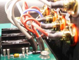
High-speed
sealed relays used for fast QSK. |
To
avoid a premature death of your amplifier, remind you as a thumb
rule that in decreasing the temperature of your active components by
10° you can double the lifetime of the power stage. Even if this
rule is empiric do never push your amplifier too far, in both power
and temperature; nominal working conditions are far better to the
maximum. Of course this rule is also valid for tubes amplifiers.
T/R
switching
In
old amplifiers the T/R (Transmit/Receive) switch is a mechanical
relay working at about 15 ms that can not switch fast enough to
allow amateurs to operate fast break-in (QSK) in modes like CW,
SSB-VOX or AMTOR. Indeed in these applications is it requested that
the switching reaches or is below 3 ms.
To
get this speed solid-state amplifiers use circuits made of high
power PIN diodes
or still better, miniature high-speed sealed relays, which are rated for millions of
operations in a life. To prevent "hot-switching" carrier-on
timing in inserted in the exciter what delays the application of
drive until relays have switched. This method extend the relay life.
Some amplifiers offer a feature that "drills" all relays
in the amplifier, low-pass filters and optional automatic antenna
tuner by operating and releasing them periodically when the amplifier is
switched on in idle mode.
2d
part
ALC
and linearity
|