|
Technical review
How
to select a tube HF amplifier ? (III)
Power
supply
After
the vacuum tube(s) the next most expensive component of a power
amplifier is the high voltage (HV) power transformer. If the use of
russian tubes can decrease the price of your amplifier, technically
speaking it is very hard to reduce the price of wires, coils and
magnets, and therefore the power supply unit (PSU) remains the stumbling block of your budget.
The
amplifier PSU has to be designed to provide
the required power. The requirements and therefore the design of the
amplifier will differ from small audio amplifiers specs to power amplifiers
(kW-class).
The power efficiency of
such an amplifier being important, this factor has effects on its sizes,
weight, power consumption and dissipation. This last requests special devices for cooling
and to respect the thermal stability of the amplifier.
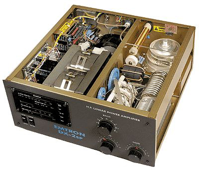
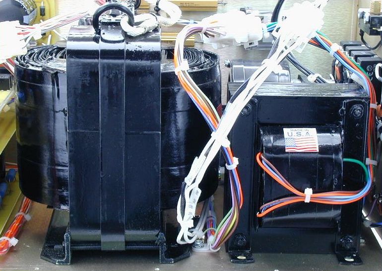
Transformers As
shows very well the picture of the Emtron
DX-2SP displayed above as well as closeups displayed below,
transformers are the most cumbersome elements of an amplifier, the
heaviest too. Such
transformers are about 20x15x10 cm in size (8x6x4") and their weight exceeds
20 kg (40 lbs.) ! Therefore some manufacturers send the PSU separate from the
amplifier itself, to the amateur to made the assembling.
A
transformer is just a piece of iron with a pair of wires coiled
wounded around it - one with many more turns in the coil than the
other. The coils of wire are not physically connected. In the
largest power transformers the iron core can be immersed in an
insulating oil bath which does not conduct electricity well.
How
works a transformer ? Basically a conductor, such as a copper wire,
is sitting in a magnetic field that is changing, and thus a current
will flow in the conductor. This current will not be steady but will
also be changing. Alternatively, if a changing current is present, it will
produce a changing magnetic field of 50 or 60 Hz.
A transformer works only with alternating current (AC)
circuits. The AC current enters the primary coil. A magnetic field
is produced that is concentrated in the iron core of the
transformer. A secondary coil of wires (also conductors) is wrapped
around the iron core, not physically touching the first set of
wires. The changing magnetic field produced by the first coil is
experienced by the second coil and current begins to flow in these
wires as well. The second coil has many more turns of wire and
offers a higher resistance to the current flow than the first coil.
The greater resistance means that a larger voltage drop (than is
present across the first coil of wire) is produced from one end of
the coil to the other. Therefore a low voltage enters the
transformer and a high voltage exits, or vice versa.
Most
transformers operate at high efficiency transmitting about 99% of
the power that enters them. About 1% of the power is lost in heating
the transformer.
 |
 |
 |
|
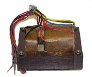
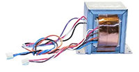
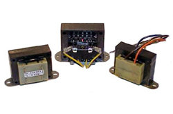
CV
Ferroresonant transformer |
Control
transformer |
Class
2 transformer |
|
There
are many kinds of
transformers : audio, class 2, CV-ferroresonant,
power isolation, control, flyback, pulse, encapsulated, sense
transformers, autotransformers, switchmode, inductors/chokes,
toroids, current transformers, 3 phase transformers, power factor
correction, high voltage, and more. In radio applications the
ones that interest amateurs are mainly inductor/choke transformers,
toroids and power transformers. Their specifications vary depending
the application and power requirements. Don't be surprised to find
in kW power amplifiers one or more toroid transformers of about 10
cm diameter and 4 cm high or a big one 22 cm diameter and 8 cm high.
The "small" one weighs about 5 kg, the larger exceeds 12
kg.
Plate
supply
An
HF amplifier used at legal limit needs a distinct plate transformer separate from
the filament transformer and control power supply. The plate supply should be
able to handle 1.5 kW continuous in any mode. In full key-down CW ouput for example, a 3 kV plate supply
should be able to sustain 700 mA. A plate
supply capable of this DC current in a B+ line should have a filter capacitor
bank of about 60µF, with a surge voltage no less than 1.41 times
the peak plate voltage.
 |
 |
|
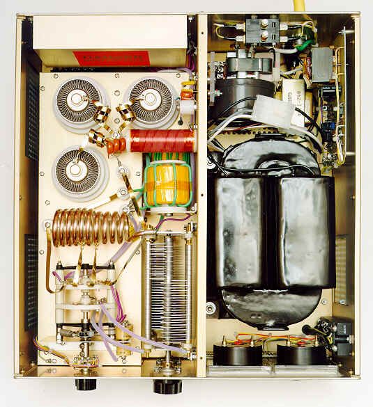
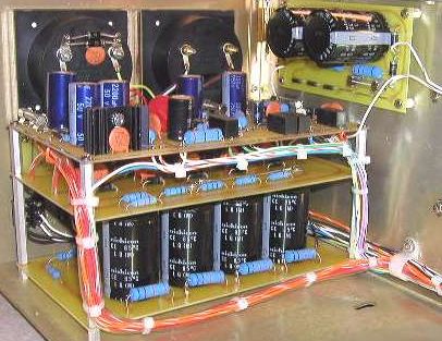
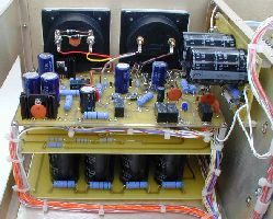
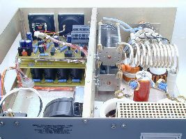
All
a compartiment, so half the volume of this QRO
HF-2500DX amplifier is dedicated to the power
supply and its circuits boards. At left, inserted
between the high grade electrolytics capacitors and
the control boards is the HV rectifier board. We can
see the twenty N5408 rectifier diodes that provide
5000 PIV capacity for DC smoothed and filtered by the
eight electrolytic capacitors located below. At right,
above the HV rectifier is the control board. It
provides LV bias, screen trip and control circuitry.
The smaller circuit board mounted at right is the
screen supply board. |
|
Rectifier
board
A full wave bridge rectifier
board in the plate supply is a must. This HV rectifier board contains some dozen rectifier
diodes (N5408) in a bridge arrangement, providing for a 3kV plate PS a total voltage rating of 5
kV PIV for DC smoothed, and filtered by several high grade electrolytic
capacitors.
Electrolytics
capacitors
The
best electrolytics are the ones that can endure years of heat in an
amplifier. So they can be top grade, as the ones used in computers, or
even oil filled models. Like tubes, it is essential to place them in a
well ventilated cabinet fixed on an insulated bracket.
|
|
 |
 |
|
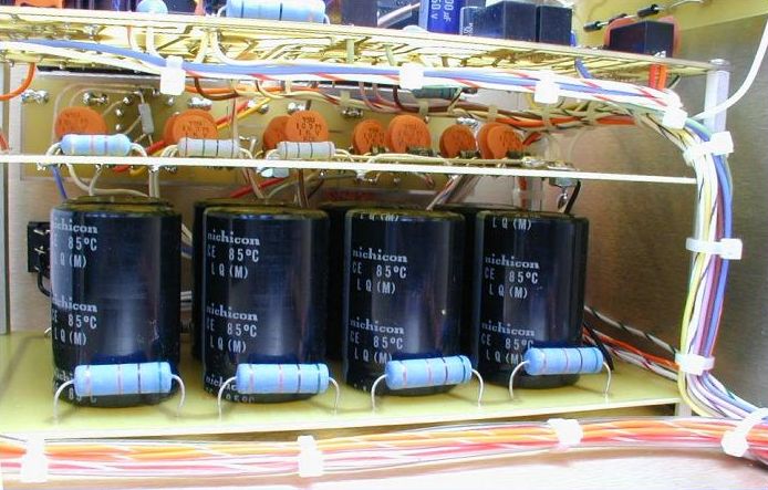
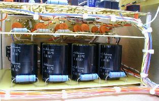
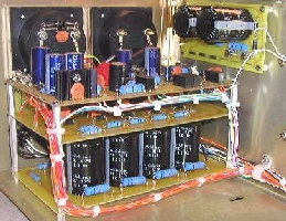
At
left, inside a Ranger 811H amplifier we discover the
PSU in the upper right part showing the EHT
capacitor stack mounted on a board. Below are two
toroidal transformers of about 5 kg each. At center
the filter capacitors (116mF,
3.6 kV) attached to the PSU of an Emtron
DX-3 amplifier. At right, in this QRO
HF-2500DX the electrolytics capacitors are located in
the left compartment. |
|
Bleeder
resistors
A
bleeder resistance is a resistance connected across the output
terminals of the power supply. Its functions are to discharge the
filter capacitors as a safety measure when the power is turned off
and to improve voltage regulation by providing a minimum load
resistance. The time lapse required to drain the high charge of the
power supply can vary from a fraction of a second to several
hours in worst cases... Contrarily to the past where amplifiers used
filter chokes and large bleeder resistors drawing 10% of full load
current on the power supply to dissipate all the heat, modern
amplifiers needs only a bleeder able to draw barely 1% of the load
once the amplifier shut down. To meet this requirement a resistance of
100-500 KW across the entire
filter bank will do that job. There are two possibilities : either
using individual resistors ranging from 68-75 KW
3-5 watts each or a single power resistor of 100-200 watts depending on the resistance.
|
|
|
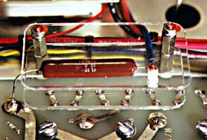
The
glitch resistor installed in the Heathkit SB-200 power amplifier. |
At
last to prevent any overheating and shorten the capacitors life span,
it is recommended to mount the bleeder resistors away from the capacitors
bank.
Glitch
resistor
As
all powered devices, an amplifier can always be subject to a surge. AC
line fuses are far to offer sufficient protection against current limits.
Therefore a glitch resistor is recommended in series with the HV lead,
even is some amplifiers have an electronic plate over-current
circuit. Made of vitreous enamel insulated wire-wound type this
resistor acts either as a "fuse" and will explode in
opening the circuit to protect the power supply or as a barrier
against current. It the first case it is recommended to use a 0.68
ohm 1-2 watts resistor in serie in the B+ line and in the second
case a 50 ohm 50 watt power resistor to limit the B+
current; this latter has for function to not "fuse".
Wiring
At
last, examining how wires are attached and how connections have been soldered in an amplifier you can
immediately recognize the sign of a quality material manufacturer.
Avoid amplifiers in which wires looks like a mesh or which circuits
show dark or too large soldering, extended-wrap connections and wires
of too small size, sign of amateur work. On the contrary choose a model
in which wires are thick, and the wiring circuit well laid out, solderings
bright, tie-wrapped. The connection to the other modules should be made via
a wire loom, and grounded to the chassis.
For
security purposes wires constituing the AC primary should be at least
#12 AGW in size (inner Ø2.07 mm), while the HV wiring should be
made of heavy Teflon or silicone rubber insulated, and no less than
#18 AGW in size (inner Ø1.16 mm).
 |
 |
|
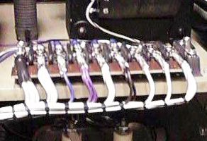
At
left, the wiring in the power supply compartment of the QRO
HF-2500DX Mark III amplifier. This section is
totally separate from the RF compartment with a
stainless steel pane. Teflon dominate in this high
quality amplifier. At right, the wire loom of a Henri
Radio amplifier. Does your actual amplifier shows
a similar quality ? |
|
Shielding
All
sections of an amplifer, the PA stage, Pi-network, controller
circuits, power supply unit, etc should be totally insulated and
enclosed in individual shielded compartment within the amplifier
chassis. Power lines and control leads should enter these shielded
enclosures via feed-through capacitors.
In
the RF section all interconnect wiring should be made of coaxial or
shielded wire. "RF" and "non-RF" wires
have also to be separate and never be found
side by side in the same area. "RF" wiring for example
should be isolated in its unit away from the other wires, like
should be the full Pi-section to avoid side effects due to RFI. RF
interconnecting cables should have their braiding grounded at shield
entry points. Lead dress should be used.
These
protecting measures will maintain RF integrity, minimise internal RF
feedback, and ensure regulatory electromagnetic compatibility (EMC)
compliance.
Last chapter
Security
issues
|