|
|
|
Basics of antennas
Gain and radiation pattern (III) Nobody
could never tell you exactly why an antenna radiates and what are
radio waves... A conductor like an antenna is constituted of metal molecules which electrons
are more or less free depending on the level of ionization of the
matter. When excited by the signal emitted by the last stage of your
transceiver, electrons contained in the charge (antenna) see their energy level
increasing and move faster, generating higher current and inducing voltage.
Together all
these small variations of current and voltage produce electromagnetic waves, a
simultaneous displacement of energy in all three dimensions that leave
the particles at the speed of light (~300000 km/s) and that move without
support away from the source, like waves propagate on the water
surface.
This
is an excellent model but say immediately that it is still
far to represent the true nature of waves that sometimes act
also like particles... But go with it ! To work properly, a transmission antenna must display the best efficiency, the strongest EM field (often in some directions), and a radiation pattern compatible with the activity (DXing or local QSOs). For a receive antenna, the problem is different. The listener doesn't care about the efficiency of his or her antenna as long as the receiver is able to pick up the weakest signals. In other words it must display the highest selectivity, the ability to respond to a tuned station and to reject any nearby undesired signal, for short it must be able to display the best S/N ratio in all circumstances. For the licensed amateur searching for an efficient antenna to "work the world", in practice that means that he or she has to check how the energy of the antenna is radiated, under what angles and what intensity. To profit at best of these properties, we must define two major terms that characterize the performances of any antenna : - The gain - The radiation pattern Gain and field strength Once powered, an antenna acts like any electrical conductor and radiates an EM field. Like any other source of energy, we can measure the amount of energy its radiates into space. You can imagine an antenna like a bulb. When powered, it radiates in all directions with a power of say 100 W. If you place your bulb close to a parabolic reflector like a flash light, all its energy is radiated in a specific direction to the detriment of the others. Your bulb produces always the same 100 W of power, but this time its energy is concentrated in a short beam from 30 to 150° wide for example; your bulb offers some directivity and its light looks brighter. An antenna works exactly in the same way. According to the proximity of a reflecting element, you can favor some directions of radiation. Note that we have always not speak about gain. Why not ? By definition the gain is a contribution to something. To get a "gain antenna" you need of an external source of energy that will provide additional HF current on the specified frequency. This kind of antenna is called an active antenna (e.g. active whips, active magnetic loops, etc). What we usually call the "gain" of an antenna is in fact the way that the radiated energy moves from an omnidirectional pattern to a favored direction, becoming directional. Say in another way, an antenna produces some energy. In the best case, it displays an increasing of EM field, a gain, in the direction of its main lobe, but in the same time it shows an equivalent loss (of gain) in all other directions. Globally, the output power stays the same, and thus this antenna has no gain strictly speaking. So, when we speak of gain of an antenna, we measure its directivity associated to its efficiency. Indeed, the directivity of an antenna depends on its radiation pattern but this latter does not tell anything about power losses that may occur in the actual antenna system (transmission line and ground). The gain of an antenna is the amount of energy radiated by the antenna main lobe compared to the energy radiated by an isotropic antenna, of course calculated with 100% efficiency (i.e. all energy is transfered to the system or the ratio received energy over arriving energy is 100% or the power ratio Pout/ Pin = 1). That means that a directional antenna showing a 6 dB gain radiates 4 times more power in the concerned direction than an isotropic antenna that radiates evenly in all directions. To
be accurate, the gain G of this antenna is a power ratio, function of
its directivity D and efficiency k : G
= k P/Pavg = kD where
G is expressed in dB (10
times the common logarithm of the power ratio or 20 times the common
logarithm of the voltage ratio). What
represents this gain in the field ? To
compare performance of a 20 dB gain antenna over an isotropic, let's
image that this antenna radiates its 20 dB gain (in fact 20 dBi)
from the center of a sphere. This energy will travel through a
surface 100 times smaller than the total surface of the sphere, or
41253° / 100 = 41° of beamwidth. The
directivity of an antenna is the maximum gain compared to its
gain averaged in all directions. The
directivity D of an antenna is given by the next relation : D
= Pd / Pd (avg) where
Pd is the power density or irradiance (output power per
surface unit) at its maximum point on the surface of the radiating sphere and Pd
(avg) is the average power density. See
also this page for more details on the
calculation of antenna efficiency, gain and directivity. Note
that the power density Pd can be calculated from
the Equivalent Isotropic Radiated Power (EIRP, in watts) : EIRP(W)
= Gain(dBi)
x Ouput Power(W) Pd
(W/m²)
= 0.0795 x EIRP / d²(m) where d is the distance from the
emission source.
As
many array antennas display a very high efficiency (SWR is often
below 1.5:1 on multi-band beams with very few losses), amateurs tend
to consider the gain essentially equals to the directivity. In first
approximation this equivalence is thus correct.
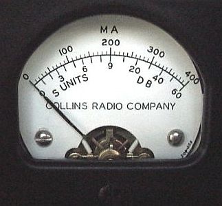
A
vintage Collins S-meter In
other words, in searching for a directional antenna, radio amateurs
seach in fact an antenna offering the greatest power gain in order
to get the sharpest lobes, I mean the directive
radiation pattern as narrow as possible in the
"line-of-fire" of their "gun". As
we told, gain is the ratio of power levels (sometimes of voltage level) and it is expressed in decibels (dB).
In other words, the value indicated on your S-meter is an absolute
value that must be compared to another system. You know that the shape of the
radiation pattern indicates how the antenna concentrates its
power. A vertical for example spreads its signals out evenly
(it is omnidirectional) and thus covers the world evenly without
directivity. Therefore using such an antenna you hear much noise on
bands compared to a more directive aerial.
But
if you can create lobes on your aerial, using for example a 5/8l
vertical, a dipole or a beam, the signal will concentrate in its
main lobe while distributing much less energy off its sides. The
aerial became directive.
If
you superimpose radiation patterns of a vertical and a dipole or the
one of a dipole and a beam and you look them straight down to the
ground you will observe that the vertical is most of probably
omnidirectional, center on its axe while the dipole displays a
8-figure shape, and the beam a cardioid pattern very extended in a
specific direction.
How
to compute the gain ? The gain offered by a beam vs. a dipole for
example is represented by the part of the beam pattern that extents
over the dipole one; this extension represents the increased range
accessible to the beam. The best way to measure this gain, thus its
field, is to request a "true" RST report to all hams contacted in local
and DXing QSO.
Some will give you low values, other very high ones
with probably a skip distance of a few hundreds to some thousand kilometers
around your QTH depending on the frequency. Repeat this measurement
all through the year because propagation conditions will affect your
results. After have accomplished this estimation 360° around you and have
contacted as much countries or zones as possible, the compilation of the data
will help you to draw the radiation pattern of your aerial with its
amplitude. A more accurate method is using a device known as a
Field Strength Meter.
Radiation
pattern : takeoff angle and height above ground We
can measure the radiation pattern of an antenna in both azimuthal and elevation planes which are a representation of the manner
that its energy, its field force, is distributed in the air. Its shape is not
small and usually exceeds several thousand kilometres. To compute this pattern,
we can use simulation programs (e.g. EZNEC,
Smith charts from AC6LA, HFANT,
etc), antenna analyzer or even a vector
newtork analyzer (very expensive) or simplier, to work on site with a
field strength meter, avoiding to touch the antenna while radiating, Hi !
To
download : HFANT
antenna modeling program Freeware
included
in the VOACAP
propagation package The
length of a dipole (1/2l) L
(meters) = 142/f or L (feet) = 468/f The frequency f
is expressed in MHz, including a reduction factor of 5% due to
the technical considerations like the conductor diameter and
length, the feeder impedance, the use of insulators and
distance from nearby objects. QRG 3.8
MHz 7.05
MHz 14.2
MHz 18.1
MHz 21.1
MHz 24.9
MHz 28.5
MHz L
(m) 78.9m 37.4m 20.1m 10.0m 7.8m 6.7m 5.7m 4.9m L(
Ft) 260' 123.1' 66.4' 32.9' 25.8' 22.2' 18.8' 16.4' When
an aerial like a dipole is powered and tuned on, at resonance the voltage is maximum
(high impedance) at the end of the line while the current is maximum
at the centre. This is from the shape of the current radiation
pattern that your aerial will pick up with more or less success
the electromagnetic field – radio waves - transmitted by other stations. The
radiation pattern of an antenna can be displayed in two kinds of
graphics : those displaying the E-plane (or E-field for Electric
field) and the H-plane (or H-field for magnetic field), and those
showing the Azimuthal (0 to 360°) and Elevation planes (0 to 90°
on front and rear sides). For
a Yagi placed over ground instead of in free space, the E-field is
parallel to the earth. We say that the antenna polarization is
horizontal. Its E-field response is usually referred to its azimuth
pattern. Its H-field response is referred to its elevation pattern. The
angular width of the E-plane main lobe at the half power, or 3 dB
down compared to the peak, represents the beamwidth. It is about
60° for a 3-element HF beam and as narrow as 13° for a 6-element
Yagi placed 1l
over ground. We can already thus conclude that if you want to work
DX stations in good conditions, it will be necessary to use a
directional array showing a narrow radiation beam to avoid loosing
the output power in all directions. At
left and center, the radiation patterns in H and E-planes of a
rhombic (wire) antenna offering a gain of 9 dBi. At right, its
coverage map. Documents Antenna.be. Basics
of electromagnetism say that a signal pick-up of a 1/4l
aerial records its maximum strength at right angle (90°) to the
line of the wire. So in its simplest version the pattern of a long wire
in polar plot is circular viewed end-on, offering either gain
nor directivity. On the other side, a dipole will concentrate its power in two
opposite directions at the expense of the two others (off the end of
the dipole); it will even display several secondaries lobes at low
angles as the antenna is higher above the ground (from 1/2l to 1l). If
the aerial is 1l long the maximum
pick-up displays a 4 directions
pattern at angles of about 55° if the wire is horizontal. For a 3/2l
aerial the pattern decreases at about 40°. Longer
aerials like beverage longer than 160 m (500’) display minors
lobes opened at 50° inside the main lobes opened at 35° from the
horizontal. In
theory We
have all heard or read that aerials had to be placed high above ground
to work properly. But how the ground affects the radiation pattern
of an antenna ? What is the behaviour of this pattern when the height
is so-called inadequate ? And what become the radiation pattern when
the antenna is placed high above ground ? First
question : why the radiation pattern is affected by the ground ? In
free space (thus in theory) a 1/2l dipole
displays a gain of 2.14 dBi over an isotropic antenna that radiates
evenly its energy in all directions. Tight horizontally above a
perfect conductive ground (e.g. a copper plate), we observe that our
dipole displays 3 dBi more gain. Why ? Because instead of radiating
in a sphere, due to the presence of the earth, half of the emitting
power is reflected by the ground and is now radiated in half a
sphere, hence the additional 3 dBi gain (remember the flash light).
Its power is now about 4 times (~6 dB) the one of the isotropic
power because it is concentrated in some directions. Then
the gain (in both direction and efficiency) of this dipole depends also on its height above ground. In
theory, as the wire radiates radially in all directions, the energy
radiated to the ground is reflected back and, under some conditions, it is added to the direct wave transmitted by the
antenna. What are these conditions ? Grounds
offering the best quality in terms of conductivity and
dielectric constant are the salt water, pastoral/low to
medium hills then rocky or sandy soils. Cities and
industrial areas are very poor. At
some determined heights above ground, the direct and
reflected waves and 100% in phase and their signals add.
This occurs when their path difference is equal to a
multiple of 1/4l. In the field
that means that if you place your antenna at 1/2l
or 1l high, the E-field radiated
by your antenna will still be doubled, you gain 3 dB more !
Now, compared to an isotropic antenna, your dipole displays
a theoretical gain of 2.14 + 3 + 3 = 8.14 dBi ! But
I suspect that you should be very happy to find such an
antenna, because no dipole displays such a high gain... Why
? Because ground properties (conductivity and dielectric
constant as displayed at left) are never perfect and
performances of your antenna depend also on its fire angle
and its physical sizings. First,
some parts of the energy radiated by the antenna is absorbed by the
ground. Its amount depends on the frequency and the soil properties.
Usually you can loose up to 50% of your output power in the lower
frequencies. In the worst case, you can loose up to 80% of the
output power on 3.5 MHz, it represents a lot of dB ! Then
if your takeoff angle is vertical (90°) you loose a maximum of
power in the ground (about 2.25 dBi). If you can manage a low
takeoff angle below 30° the typical absorption decreases of 50%. In
practice, that means that your 8.14 dBi dipole tight at 1/4l
but radiating almost at 90° due to its low height above ground,
displays a gain of only 5.89 dBi ! In
practice Now
the other two questions, that we can summarize in analyzing
how the height affects the radiation pattern of an antenna. The
next experiment will help us to answer to this question. In
all ham activities, DXing or working locally, we sometimes
need directivity and high-gain antennas and at other
times omnidirectionality is very appreciated when working
with networks for example or to contact close stations. In all cases the potential of our
antenna depends on its height above ground and in a
lesser extend on its design. So what is
the best height ? According
to various experimenters and specially ARRL that installed
dipoles for the 80 m band from 0.05l
(40 cm) to 4l
(320 m !) above the ground the resultats are the following : Height
(l) Height
(m) Takeoff
angle dBi
front Feed
line (W) 1/10 4 90° 8.21 8.21 23 This
table is of course valid with very few changes for any other HF frequency as we
speak in term of "working frequency" l. In
short, we observe that the gain in the favored, broadside
direction of the dipole varies very little with heigth while
the pattern of the takeoff angle of the primary loop changes
much. Closer is the antenna to the ground, higher is the
takeoff angle with a pattern close to the one of a vertical
below 1/3l
high. This explains comments saying that a dipole must be at
least 1/2l
high to work properly on DX.
We
also see a strong asymmetry of gain between the broadside
and the ends of the dipole (4th and
5th columns that express
values for the secundary lobe with the lowest launch angle).
The best results appear for 1l
where the axial direction displays a "negative
gain" of -11 dBi while the broadside has a +7.64 dBi
gain (+5.5 dBd) ! Radiation
patterns for an horizontal dipole placed at various
heights above a flat ground off the ends of the
antenna wire (not as seen from the side). The
dielectric constant of earth k = 13, the
conductivity of earth G = 0.005 S/m. The absolute
gain in dBd in free space is about 10% higher. If
there was no reflection from the ground (in free
space) all patterns should be circular (spherical)
due to the omnidirectional radiation around the
conductor. The
feed line impedance refers to an antenna length at resonance
at a height of 1/2l.
As expected the feed point impedance oscillates
significantly depending the various factors like the ground
nature, nearby objects, etc. One more time this confirms the fact
that your dipole must be trim to fit your
particular location and that the height above the ground is
very important. According
to various tests made in the field by amateurs, we observe also that at
certain takeoff angles, an antenna has more chances to reach a DX
station that at any other takeoff angle. Here is an example : Incidence
angles for best DX receiving HF
Band Takeoff
angle 10
meters :
3 - 9° 15
meters :
4 - 12° 20
meters :
6 - 17° 40
meters : 10
- 35° 80
meters :
4 - 28° Using
these takeoff angles with your antenna you have 99%
chances that your signal arrive at destination (in
this case a QSO between K and G stations). But using a
takeoff angle between these extremes (e.g. 11° for the
20m band) you have only 50% chances that your signal
arrives to the DX station. In this context a modeling
program associated to a propagation tool like MultiProp
or VOAAREA
is welcome. We
can then conclude that for DXing, the higher the
antenna above ground, the more energy will be concentrated a
few degrees above the horizon. This is achieved installing the aerial
close to 1l
high. Take also into account the intensity of the secundary
lobe in the broadside and the radiation pattern off the ends
(bad from 1/3l
and below). Contrary
to DX work, for local activity, at heights from 1/3l
and below, the dipole becomes omnidirectional with less than 1 dB of
attenuation in the end fire direction (for 1/5l
and below), which suggests to choose a height between 0.4 -
0.3l
to get an ideal compromise. Take only care to your impedance
if you install the wire at very low heights. In all other
circumstances the SWR stays near 1:1. To
close the subject, note as we explained in the pages devoded to
wire antennas for
listeners that the pickup efficiency of a receiving antenna is first of all
determined by the length of its radiator in order to pick up as much energy as
possible. But in spite of their difference of
length, HF and VHF antennas for example are both as efficient from
the moment that they are well tuned and coupled to the line and to
the RTX. But in receiving both antennas do not capture at all the
same amount of energy although their gain is maybe equivalent
compared to another antenna working on the same frequency.
For
more information
All
about transmission lines (on this site)
The
mystery of radials (on this site) From dB to S-point : Learn to play with power units
(on this site)
Antenna
height : 11 articles you need to read, DX Zone DX
Zone : Antennas
section, HF
Vertical Antenna, HF
Yagi Antenna (Search), Stealth,
Portable eHam
reviews (specially Antennas)
ARRL
Antenna Book, ARRL, specially chapter 16, 2011 (22d edition) The
ARRL Antenna
Book 1998 in PDF, QRZ.ru Vertical
Antenna Classics, ARRL, 1995/2001 Degree-amperes
and field strenght, by Edmund A. Laport (antenna currents) In
QST magazine, 1973-1976, Walter Maxwell, W2DU (sk) wrote articles
dealing with
antennas, SWR and line lossses titled Another
Look At Reflections (PDF) In QEX
magazine,
May/June
2011, p39, Alan Payne, G3RBJ wrote an interesting article about the
coil theory. In
QST magazine, September 2006 issue,
pp56-57, VE2CV explains how to use an antenna
analyzer and EZNEC to calculate the antenna efficiency (in this case
of a mobile antenna). Page 56 also describes SWR. |
||||||||||||||||||||||||||||||||||||||||||||||||||||||||||||||||||||||||||||||||||||||||||||||||||||||||||||||||||||