|
|
|
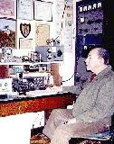
Louis Varney, SK |
G5RV Multi-band Antenna
by Louis Varney, G5RV
|
|
|
Louis Varney, SK |
On 28 June 2000, at 89, Louis Varney, alias G5RV, rejoined the large family of silent keys hams. To pay tribute to this famous radio amateur, I would like to present you one of the main work he shared with the ham community : the invention of the G5RV dipole antenna.
The G5RV, with its special feeder arrangement, is a multi-band centre-fed antenna capable of very efficient operation on all HF bands from 80 to 10m, specifically designed with dimensions which allow it to be installed in gardens which accommodate a reasonably-straight run of about 31.1m (102 ft) for the "flat-top".
Because the most useful radiation from a horizontal or inverted-V resonant antenna takes place from the center two-thirds of its total length, up to one-sixth of this total length at each end of the antenna may be dropped vertically, semi-vertically, or bent at some convenient angle to the main body of the antenna without significant loss of effective radiation efficiency. For installation in a very limited space, the dimensions of both the "flat-top" and the matching section can be divided be a factor of two to make the half-size G5RV, which is a very efficient antenna from 40 to 10m.
The full-size G5RV will also function on the 160m band if the station end of the feeder (either balanced or coaxial-type) is strapped and fed by a suitable antenna tuner using a good earth connection or a counterpoise wire. Similarly, the half-size version may be used thus on 80m and 160m bands.
In contradistinction to multiband antennas in general, the full-size G5RV antenna was not designed as a half-wave dipole on the lowest frequency of operation, but as a 1/2l wave centre-fed long-wire antenna on the 20m band, where the 10.36m (34 ft) open-wire matching section functions as a 1:1 impedance transformer, enabling the 75W twinlead or 50/80 ohm coaxial cable feeder to "see" a close impedance match on that band with a consequently low VSWR on the feeder.
|
||||
However,on all the other HF bands the function of this section is to act as a " make-up" section to accommodate that part of the standing-wave (current and voltage components) which, on certain of the operating frequencies, cannot be completely accommodated on the "flat-top" (or inverted-V) radiation portion. The design centre frequency for the full-size version is 14.150 MHz, and the dimensions of 31.1m (102 ft) is derived from the formula for long-wire antennas which is :
Length (ft) = 492 (n - 0.015)/MHz = 492 x 2.95/14.15 = ~102 ft (31m)
where n equals the number of half-wavelengths of the wire (flat-top).
In practice, since the whole system will be brought to resonance by the use of an antenna tuner, the antenna is cut to 31.1m (102 ft).
As it does not make use of traps or ferrite beads, the "dipole" portion becomes progressively longer in electrical length with increasing frequency.
This effect confer certain advantages over a trap or ferrite-bead loaded dipole because, with increasing electrical length, the major lobes of the vertical component of the polar diagram tend to be lowered as the operating frequency is increased. Thus, from 20m up, most of the energy radiated in the vertical plane is at angles suitable for dx working. Furthermore, the polar diagram changes with increasing frequency from a typical half-wave dipole pattern on 80m and a 1/2l wave in-phase pattern on 80m and 30m to that of a "long-wire" antenna on 20, 17, 15, 12 and 10m bands (Fig.1 below).
|
Although the impedance match for 75W twinlead or 80 ohm coaxial cable at the base of the matching-section is very good on 20m band, and even the use of 50 ohm coax cable results in only about 1.8:1 VSWR on this band, the use of a suitable antenna tuner is necessary on all the other HF bands because, on those bands, the antenna plus the matching-section will present a reactive load to the feeder. thus the use of the correct type of antenna tuner (unbalanced input to balanced output if twin-wire feeder is used, or unbalanced to unbalanced if coaxial feeder is used) is essential in order to ensure the maximum transfer of power to the antenna from a typical transceiver having a 50W coaxial (unbalanced) output.
|
Also to satisfy the stringent load conditions demanded by such modern equipment employing an ALC system which "senses" the VSWR condition presented to the solidstate transmitter output stage so as to protect it from damage which could be caused by a reactive load having a vswr of more than about 2:1 (Fig. 2 above)
The above reasoning does not apply to the use of the full-size G5RV antenna on the 180m band, or to the use of the half-size version on 80 and 160m.
In these cases the station end of the feeder conductors should be "strapped" and the system tuned to resonance by a suitable series-connected inductance and capacitance circuit connected to a good earth or counterpoise wire.
Alternately, an "unbalanced-to-unbalanced" type of antenna tuner such as a "T" or "L" matching circuit can be used. Under these conditions the "flat-top" (or inverted-V) portion of the antenna plus the matching section and feeder function as a "Marconi" or "T" antenna, with most of the effective radiation taking place from the vertical, or near vertical, portion of the system; the "flat-top" acting as a top-capacitance loading element. However, with the system fed as described above, very effective radiation on these two bands is obtainable even when the "flat-top" is as low as 7.6m (25 ft) above ground.
|
Theory of Operation
The general theory of operation has been explained above; the detailed theory of operation on each band from 80 to 10m follows, aided by figures showing the current standing wave conditions on the "flat-top" and the matching (or make-up) section. The relevant theorical horizontal plane polar diagrams for each band may be found in any specialized antenna handbooks. However, it must be borne in mind that: (a) the polar diagrams generally shown in two dimensional form are, in fact, three dimensional (i.e. solid) figures around the plane of the antenna; and (b) all theoretical polar diagrams are modified by reflection and absorption effects of near-by conducting objects such as wire fences, metal house guttering, overhead electric power and telephone wires, house electric wiring system, house plumbing systems, metal masts and guy wires, and large trees. Also the local earth conductivity will materially affect the actual polar radiation pattern produced by an antenna.
|
Modification for 160m To work on 160 meters with such a dipole, use a simulation software like EZNEC or the freeware DIPOLE3 and change lengths of the dipole, feedline, etc until you get a good efficiency (a low impedance and SWR with very few losses). For your information, if you place the dipole 11m high above ground and using a 10.35m long ladder line for the matching section you could get an efficiency of 40% but only... in extending the dipole to 84m and using 15m of coax. Your VSWR on the feedline will be ~13:1, with 3.8 dB of overall loss or 0.5 S-points. Less than half of your power will be emitted in such conditions... The best efficiency, 81%, is got using 45m of Belden 9913 coax and placing the dipole 40 meters high ! |
Theoretical polar diagrams are based on the assumptions that an antenna is supported in "free space" above a perfectly conducting ground. Such conditions are obviously impossible of attainment in the case of typical amateur installations. What this means in practice is that the reader should not be surprised if any particular antenna in a typical amateur location produces contacts in directions where a null is indicated in the theoretical polar diagram and perhaps not such effective radiation in the directions of the major lobes as theory would indicate.
|
80m. On this band each half of the "flat-top" plus about 5.18m (17 ft) of each leg on the matching-section forms a fore-shortened or slightly folded up half-wave dipole. The remainder of the matching-section acts as an unwanted but unavoidable reactance between the electrical centre of the dipole and the feeder to the antenna tuner. The polar diagram is effectively that of a half-wave antenna (Fig.4 above).
40m. The "flat-top" plus 4.87m (16 ft) of the matching section now functions as a partially-folded-up "two half-wave in phase" antenna producing a polar diagram with a somewhat sharper lobe pattern than a half-wave dipole due to its colinear characteristics. Again, the matching to a 75W twinlead or 50/80 ohm coaxial feeder at the base of the matching section is degraded somewhat by the unwanted reactance of the lower half of the matching section but, despite this, by using a suitable antenna tuner the system loads well and radiates very effectively on this band (Fig.5 below).
|
30m. On this band the antenna functions as a two half-wave in-phase colinear array, producing a polar diagram virtually the same as on 40m. A reactive load is presented to the feeder at the base of the matching section but, as for 40m, the performance is very effective (Fig.6 above)
20m. At this frequency the conditions are ideal. The "flat-top" forms a three-half-wave long centre-fed antenna which produces a multi-lobe polar diagram with most of its radiated energy in the vertical plane at an angle of about 14°, which is very effective for DXing. Since the radiation resistance at the centre of a three-half-wave long-wire antenna supported at a height of 1/2l above ground of average conductivity is about 90 ohm, and the 10.36m (34 ft) matching section now functions as a 1:1 impedance transformer, a feeder of anything between 75 and 80 ohm characteristic impedance will "see" a non-reactive (i.e. resistive) load of about this value at the base of the matching section, so that the VSWR on the feeder will be very nearly 1:1. Even the use of 50 ohm coaxial feeder will result in a VSWR of only about 1.8:1. It is here assumed that 10.36m (34 ft) is a reasonable average antenna height in amateur installations (Fig.7 below).
|
17m. The antenna functions as two full-wave antennas fed in phase; combining the broadside gain of a two-element colinear array with somewhat lower zenith angle radiation than a half-wave dipole due to its long-wire characteristic (Fig.8 above).
15m. On this band the antenna works as a "long-wire" of five half-waves, producing a multilobe polar diagram with very effective low zenith angle radiation. Although a high resistive load is presented to the feeder at the base of the make-up section, the system loads very well when used in conjunction with a suitable antenna tuner and radiates very effectively for DX contacts (Fig.9).
|
12m. The antenna again functions effectively as a five-half-wave "long-wire" but, because of the shift in the positions of the current anti-nodes on the flat-top and the matching section, as may be seen from Figure 10 below the matching or "make-up" section now presents a much lower resistive load condition to the feeder connected to its lower end than it does on the 15m band. Again, the polar diagram is multilobed with low zenith angle radiation.
10m. On this band, the antenna functions as two "long-wire" antennas, each of three half-waves, fed in-phase. The polar diagram is similar to that of a three half-wave "long-wire" but with even more gain over a half-wave dipole due to the colinear effect obtained by feeding two three-half-wave antennas, in line and in close proximity, in-phase (Fig.11).
|
The Antenna
The dimensions of the antenna and its matching section are shown in the drawing displayed below. The "flat-top" should, if possible, be horizontal and run in a straight line, and should be erected as high as possible above ground. In describing the theory of operation, it has been assumed that it is generally possible to erect the antenna at an average height of about 10.35m (34 ft), which happens to be the optimum radiation efficiency on 160, 80 and 40m bands for any horizontal type antenna, in practice few amateurs can install masts of the optimum height of half a wavelength on 80 or 40m, and certainly not on 160m.
If, due to limited space available, or to the shape of the garden, it is not possible to accommodate the 31.1m (102 ft) top in a straight line, up to about 3m (10 ft) of the antenna wire at each end may be allowed to hang vertically or at some convenient angle, or be bent in a horizontal plane, with little practical effect upon performance. This is because, for any resonant dipole antenna, most of the effective radiation takes place from the centre two-thirds of its length where the current antinodes are situated. Near to each end of such an antenna, the amplitude of the current standing wave falls rapidly to zero at the outer extremities; consequently, the effective radiation from these parts of the antenna is minimal.
|
|
The
antenna may also be used in the form of an inverted-V. However, it
should be borne in mind that, for such a configuration to radiate at
maximum efficiency, the included angle at the apex of the V should
not be less than about 120° (although many authors consider an
opening between 90-120° only); The use of #14 AWG (inner Ø
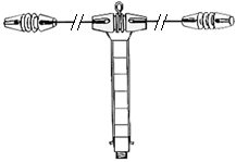
The Matching Section
This should be, preferably, of open-wire feeder construction for minimum loss. Since this section always carries a standing-wave of current (and voltage) its actual impedance is unimportant. A typical, and very satisfactory, form of construction is shown below. The feeder spreaders may be made of any high-grade plastic strips or tubing; the clear plastic tubing sold for beer or wine siphoning is ideal.
|
If it is desired to use 300W ribbon type feeder for this section, it is strongly recommended that the type with "windows" (ladder line) be used because of its much lower loss than that with solid insulation throughout its length, and its relative freedom from the "detuning" effect caused by rain or snow. If this type of feeder is used for the matching section, allowance must be made for its velocity factor in calculating the mechanical length required to resonate as a half-wave section electrically at 14.150 MHz. Since the velocity factor of standard 300W ribbon feeder is 0.82, the mechanical length should be 8.5m (28 ft). However, if 300W ribbon with "windows" is used, its velocity factor will be almost that of open-wire feeder, say 0.90, so its mechanical length should be 9.3m (30.6 ft). This section should hang vertically from the centre of the antenna for at least 6.1m (20 ft) or more if possible. It can then be bent and tight off to a suitable post with a length of nylon or terylene cord so as to be supported at above head-height to the point where, supported by a second post, its lower end is connected to the feeder.
The Feeder
The antenna can be fed by any convenient type of feeder provided always that a suitable type of antenna tuner is used. In the original article describing the G5RV antenna, then in RSGB bulletin November 1966, it was suggested that if coaxial cable feeder was used, a balun might be employed to provide the necessary unbalanced-to-balanced transformation at the base of the matching section. This was because the antenna and its matching section constitute a balanced system, whereas a coaxial cable is an unbalanced type of feeder. However, later experiments and a better understanding of the theory of operation of the balun indicated that such a device was unsuitable because of the highly reactive load it would "see" at the base of the matching or "make-up" section on most HF bands.
It is now known that if a balun is connected to a reactive load presenting a VSWR of more than about 2:1, its internal losses increase, resulting in heating of the windings and saturation of its core (if used). In extreme cases, with relatively high power operation, the heat generated due to the power dissipated in the device can cause it to burn out as well as the PL jacks. However, the main reason for not employing a balun in the case of the G5RV antenna is that, unlike an antenna tuner which employs a tuned circuit, the balun cannot compensate for the reactive load condition presented to it by the antenna on most of the HF bands, whereas a suitable type of antenna tuner can do this most effectively and efficiently.
Recent experiments by Louis Varney to determine the importance or otherwise of "unbalance" effects caused by the direct connection of a coaxial feeder to the base of the matching section had a rather surprising result. They proved that, in fact, the HF currents measured at the junction of the inner conductor or the coaxial cable with one side of the (balanced) matching section and at the junction of the outer coaxial conductor (the shield) with the other side of this section are virtually identical on all bands up to 10m, where a slight but inconsequential difference in these currents has been observed. There is, therefore, no need to provide an unbalanced-to-balanced device at this junction when using coaxial feeder.
However,
the use of an unbalanced-to-unbalanced type of antenna tuner between
the coaxial output of a modern transmitter (or transceiver) and the
coaxial feeder is essential because of the reactive condition
presented at the station end of this feeder which, on all but the
20m band, will have a fairly high to high VSWR on it. This VSWR,
however, will result in insignificant losses on a good-quality
coaxial feeder of reasonable length; say, up to about 21.3m (70 ft).
Because it will, inevitably, have standing waves on it, the actual
characteristic impedance of the coaxial cable is unimportant, so
that either 50W or 80W type can be used.
Impedance
of a ladder line Assuming
that you use round wires, and air dielectric, the impedance
is approximatively : W
= 120 ln (2 . D/d) with
W,
the impedance in ohm ln,
the natural logarithm D,
the wire spacing, center to center (from 30 to over 150 mm) d,
the wire diameter (from #14 to #18 AWG) So,
to get W
ohms for a given wire diameter d, apply the next formula : D
= d*e(W/120)/2 Here
are some usual values : Impedance
(W) D/d 150 200 300 450 600 1.9 2.8 6.2 22 75
Another very convenient type of feeder that may be used is 75W Twin-Lead. However, because of the relatively high loss in this type of feeder at frequencies above about 40m, especially when it has a high VSWR on it, it is recommended that not more than about 15 to 18m (50 to 60 ft) of this type feeder be used between the base of the matching section and the antenna tuner. Unfortunately the 75W Twin-Lead in the UK is the receiver type; the much less lossy transmitter type is available in the U.S.A.
By far the most efficient feeder is the "open-wire" type. A suitable length of such feeder can be constructed in exactly the same way as that described for the open-wire matching section. If this form of feeder is employed, almost any convenient length may be used from the centre of the antenna right to the antenna tuner (balanced) output terminals. In this case, of course, the matching section becomes an integral part of the feeder. A particularly convenient length of open-wire feeder is 25.6m (84 ft), because such a length permits parallel tuning of the antenna tuner circuit on all bands from 80 to 10m with conveniently located coil taps in the antenna tuner coils for each band, or, where the alternative form of antenna tuner employing a three-gang 500 pF/section variable coupling capacitor is used the optimum loading condition can be achieved for each band. However, this is not a rigid feeder length requirement and almost any length that is mechanically convenient may be used. Since this type of feeder will always carry a standing wave, its characteristic impedance is unimportant, and sharp bends, if necessary, may be used without detriment to its efficiency. It is only when this type of feeder is correctly terminated by a resistive load equal to its characteristic impedance that such bends must be avoided.
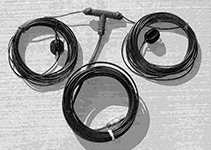
Coaxial cable HF choke
Under certain conditions, either due to the inherent "unbalanced-to-balanced" effect caused by the direct connection of a coaxial feeder to the base of the (balanced) matching section, or to pick-up of energy radiated by the antenna, a current may flow on the outside of the coaxial outer conductor. This effect may be considerably reduced, or eliminated, by winding the coaxial cable feeder into a coil of 8 to 10 turns about 15 cm (6") in diameter immediately below the point of connection of the coaxial cable to the base of the matching section. the turns may be taped together or secured by nylon cord. However this construction can become the source of problems during thundery weathers.
Water-proof you said ?
It is important, of course, that the junction of the coaxial cable to the matching section be made thoroughly water-proof and stays dry by any of the accepted methods; binding with several layers of plastic insulating tape or self-amalgamating tape and then applying two or three coats of polyurethane varnish, or totally enclosing the end of the coaxial cable and the connections to the base of the matching section in a sealant such as epoxy resin. At WiMo for example the 4:1 balun coming with their G5RV is designed such a way that it protects the SO-239 connector from the rain when it is hanged in vertical position, the coaxial being screwed over 2 cm inside the balun. However if you work with high power I warmly suggest you to place the balun and its connector inside a small home-maded weatherproof box or, better, to use a small electrical box for oudoor installations so that allconnexions stay dry.
Have fun with G5RV !
How to tune a 40-meter dipole antenna on 15 meters ? Louis Varney didn't deal with this solution that can be very useful if you want to work with a half-size dipole cut for 7 MHz (about 20m long) on harmonics like the 15m band. But we all know that this wavelength is out of band for phone work (USB) in most ITU Regions (because 7.2 x 3 = 21.6 MHz). By what miracle can we use this dipole on 21 MHz ? The solution is really simple and consists in charging the antenna with a capacitance hat, one on each segment. How to proceed ?
Cut two-60 cm long (2 ft) pieces of thick wire (#12 or #14 house wiring) and solder the ends of each piece together to form 2 loops. Twist the loops in the middle to create a two figure 8s. Solder the twisted centers of your figure 8s to each leg of your dipole at a point about a third of the way from the feed point (position is not critical). Adjust the loop shape and take measurement on 15m band until you reach an acceptable SWR on your working frequency. You SWR on 40m should only see a minor variation. |
Have fun with the G5RV !
For more information
http://www.universal-radio.com/
http://www.hfantennas.com/
http://usa2way.homestead.com/
http://www.mapleleafcom.com/
http://www.wsplc.com/
http://www.mfjenterprises.com/
http://www.sarradio.com/
Jim Thompson's FAQ Book :
http://www.radioworks.com/Book/82/82.html
A summary of this article was printed in RADIO COMMUNICATIONS, July 1984.
Extracted from LX4SKY website at http://www.astrosurf.com/luxorion/qsl-g5rv-print.htm
* *
*