|
|
|
The History of Amateur Radio
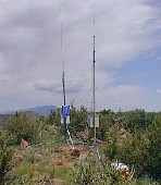
The 1970s : The FM repeaters (XIII) After the shy birth of relay stations or repeaters on 5 meters in the 1930s, and their quasi "secret" use in mobile operations in the '50s in AM, it was now great time to remind to all amateurs that FM repeaters were capable to handle with a great efficiency VHF and UHF traffics. Beside repeaters used by professionals in transcontinental and transoceanic transmissions, amateurs took advantage of this technology for a simple reason. In areas where signals travelled over long distances, in V/UHF they observed a strong attenuation and, in some areas, it was impossible to transmit data by shortwaves. These signals needed to be reamplified somewhere on the path to be retransmitted at a higher level without signal loss. Originally used with telegraphy, today repeaters are also used in telephony and data communications (computing networks). Most repeaters look like a cellular phone pylon set up on a high point, a tower or a building roof, often in a radius less than 30 km around your QTH. Others however are specially dedicated to support scientists working in remote areas, far from any communication medium. These portable installations, like the one displayed at right relay for example remote weather data to a central weather office located up to 100 km away in the valley. The method of retransmission is simple. The user activates the relay in sending a DTMF tone at some frequencies (e.g. 750 Hz during 3 seconds). Then the relay identifies itself, giving its call sign and some additional information like the working frequencies (TX, RX). Here is an example of a recent Echolink relay installed at Honolulu, Hawaii, NH6XO-R. Once activated using the DTMF function of your UHF transceiver tuned on 443.775 MHz, you listen this welcome message. Then call CQ to enter in contact with other hams as you will do usually. Of course nowadays Echolink and other IRPL allow you to get the same access through the Internet, the transceiver being connected to a computer linked to the web.
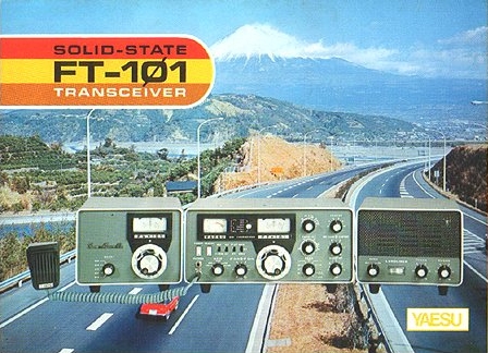
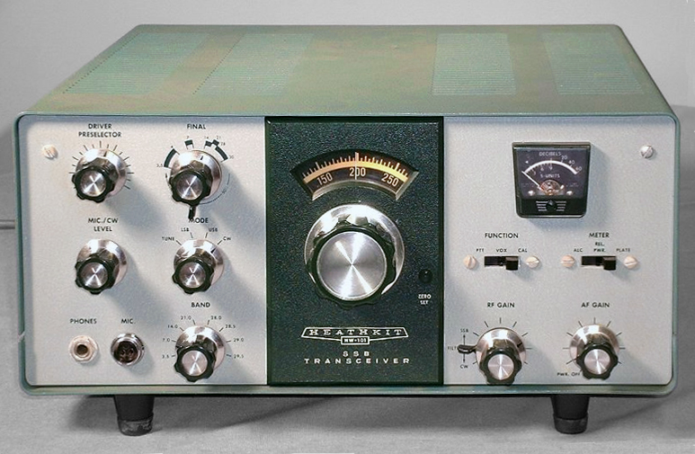
During the '60s, pushed by the boom of mobile FM that occured twenty years earlier just after WW II, manufacturers provided at commercial purposes mobile FM transceivers but they were not really tightened up to their own channel spacing. This displeased to FCC who required an adjustement and the respect of the regulation. Suddently manufacturers had in stock thousands of useless but performing hand-held and base FM transceivers that worked already on the 6-meter, 2-meter and 70-cm bands. They modified them to requirements of FCC, and quickly these low cost gears appeared on the secondhand market. Rapidly manufacturers adapted to the new demand, and in the '70s FM repeaters knewn a great expansion to both amateur and professional use who had a choice among tens of hand-held transceivers to work remotely on FM. The first FM scanners (receivers) were introduced at that time. In 1972 there were not less than 310 VHF repeaters in the USA and 52 in Canada ! These FM transceivers worked not only on the 2-meter but also on the 1.5-meter (200 MHz) and 70-cm bands. One of these model was the Standard C-826M, a 12-channel FM transceiver quickly rejoigned by the "Bearcat" scanner 800 XLT, covering only 8 FM channels. This is also in 1972 that the first customers could pay their equipment thanks to Bank of America and Master Charge credits cards. This means of paiment was only imported in Europe in the '80s. In 1970, the Japanese equipment continued penetrate in the market. While Kenwood introduced its JR-500SE receiver and prepared the blue prints of its first transmitter (TS-120S in 1979), in less than 6 months Yaesu released two transceivers, the FTdx-560 and FT-101. Stateside, Drake released its Drake TR-4, Henry Radio introduced its Tempo-One transceiver and Heath announced the HW-100 and soon after the HW-101, two traditional tube-type SSB transceivers.
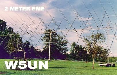
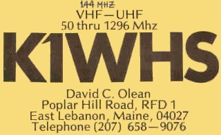
Development of EME activities During the '70s we saw also a larger number of amateurs working with EME thanks to some oversized stations. Among the pioneers stations name David C.Olean, K1WHS, who was active from Maine on 144.200 MHz and 432 MHz, experimenting curtains and Yagi antennas. He uses sometimes 24x 14-elements "Junior Boomer", or 336 elements steerable in both directions ! The gain was about 26 dB. For your information his HF power was about 1500 W and his feed line was 75 mm in diameter ! His echoes were powerful, up to 30 dB. He received his own echoes with only 3 W. Thanks to this station many amateurs using standard equipment get their first lunar link ! This is in the way that a belgian station that worked with only 170 W output and only one 16-element F9FT Yagi was contacted.
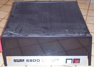
There was also Cor Maas, VE7BBG, living on the island of Vancouver. He was active on 432 MHz then 1296 MHz. He used a home-maded parabolic dish 6.5 m of diameter. His power on 432 MHz was 1200 W, and 600 W on 1296 MHz with 6x3CX100 at the final. In the '70s Cor looked like a pioneer, realizing many "première". In the '80s he was looking for correspondents in Europe on 23 cm. We can also name other amateurs who took advantage of professional installations, radiotelescopes, and other high gain dishes for Mounbounce : K3NSS, KP4NPZ, SK2CJ, ... Since that time other radioastronomy observatories have been used by amateurs like WA6LET who worked at the Stanford Research Institute in California and who used not less than the institute 50 m parabolic dish which gain was 35 dB on 144 MHz, W8IWI/8 at Green Bank (42 m) or VE3ONT at the Algonquin Radio Observatory (46 m) used by the Toronto VHF Society. Packet, when computers come on stage All began in Canada at fall 1977 when the "Groupe de Montréal" created the first concept of the packet interface. Their prototype ran in one of the first microcomputer sold in kit, the SouthWest Scientific 6800 alias SWTPC6800 based on a Motorola 6800 8-bit processor (450$ in 1975). Remember that at that time home computers were still a ghost market. On May 30, 1978 they did officially a demonstration of their system in front of the Canadian Ministry of Communications. They used a "store and forward" repeater installed on Mont Rigaud, at midway between Montréal and Ottawa, and achieved the first packet transmission between these two cities distant of 220 km. The project cost about 1000$ per station, including the radio. Remind that a "packet" is a fundamental unit of information made of a header, which contains the identification and the address of the information to send and receive followed with a data area, which contains the user's information, his data, the all constituting the datagram. Applied to amateur radio, data are the audio and the PTT keying. The protection against loss, duplication, or misdelivery of packets is usually ensured by TCP protocol located one layer down in the ISO layering standard. Over two years later, Doug MacDonald Lockhart, VE7APU, used to play with electronic kits, and working at IBM, developed an asynchronous version of X.25 protocol. Indeed, on wireless systems, signals are carry out no more by TCP/IP but by the AX.25 protocol, a version of the wired network protocol X.25 adapted to amateurs needs. However, details of AX.25 encapsulation rules may vary from country to country. But enough of theory !
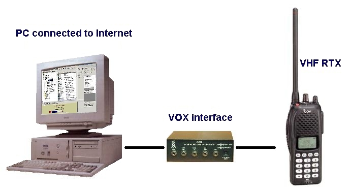
Lockhart worked with a beta version of the first PC XT and used a modem which plans were designed by Jacques Orsali, VA2JOT (ex VE2EHP) a member of the "Groupe de Montréal". This solution was in fact a kit offered to the ham community to communicate in ASCII on the air (or later through the Internet), connecting the interface between the computer and the transceiver. Unfortunately FCC didn't accepted such a digital mode of traffic and we had to wait the '80s to use this new mode and see the development of the packet radio at a world scale. So in the meantime, amateurs began to prepare their gears. As displayed at left, you need a computer, a digital interface (Pakratt, Rigblaster, etc) and any HF or VHF transceiver. But, regulation obliges, we will come back on this technology in ten (virtual) years... New L-carrier coaxial cables and development of optical fiber Meanwhile, in 1974 in the U.S.A, 30% of the interstate traffic was ensured by coaxial cable, far much that in any other European country. With the fast growing expansion of telephony, TV, repeaters and soon personal computers, AT&T invented a new "L5" coax able to sustain still heavier traffic. L5 used 11 pairs of coaxial tubes in a sheath, supporting each 13,200 voice channels. L5 could carry 132,000 calls or more than 200 television programs simultaneously ! AT&T didn't developed further this product and the majority of the coaxial routes were never upgraded beyond L4 (3600 voice circuits per channel, 10 pairs of tubes in the cable) because of the development of the optical fiber in the late '70s and digital communications.
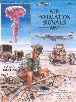
From the mid '60s to '70s, due to the potential risk of nuclear war, it was asked AT&T to provide the US Government with nuclear hardened coaxial cable, able to resist to LEMP (lightning) and NEMP (nuclear electromagnetic pulse). This highly shielded and very stiff coax connected major routes from east to the west US coast, along the the seaboard, as well as from the east to the midwest. Soon this type of coax equipped also most military facilities worldwide. Today all these lines, even is some are still used for backup operations, are replaced by fiber optics that carry much more calls, safer, without much loss, and at the speed of light. At right an interesting poster showing the Royal Engineer Signal Service providing ground communications, other than wireless, for the Air Forces in overseas, specially on Christmas Island during the nuclear weapons tests in 1957-58. It appeared soon that the NEMP interfered with transmissions. First underground cabling network in Belgium At the end of '70s, Belgium wanted to anticipate the fast growing of telecommunications and, face to the high demand of its population and the high density of its communication network, authorities decided to replace all aerials, telephony and TV with a cabling system burried a few feet under ground. This change last over ten years, and continue here and there, but soon the face of the country changed. All TV Yagis fixed of roofs used till then to receive broadcast stations disappeared like by miracle. During about tirty years Belgium was the first nation in the world to own a so dense and performing underground cabling system. But after the rising of the satellite TV in the end of '80s, new parabolic dishes appeared on balconeries, and soon the Ministery of Telecommunications had to regulate theses installations to not transform again the landscape in a telecom center as we sometimes see it in other bordering countries... WARC bands In 1979, thanks to the hard fight of IARU, the union representing ham associations at WARC conferences (future WRC), amateurs get three new HF bands : 30, 17 and 12 m (10, 18 and 24 MHz). One more time most of us had to adapt their antennas and find a way to transmit on the new frequencies. Because it is very narrow, operation on the 10-m bands have been restricted to CW and RTTY, and soon to digital modes excepted packet. However in some european countries, and in spite of the notice of IARU, some hams not aware of this regulation continue to use this band for voice. There is however few violation of the rules. The 30-m band (10,100-10,150 kHz) is assigned to the hams as fixed primary service for narrow band digimodes and CW. The 17-meter band (18,068-18,168 kHz is an ham band shared equally between the amateur service including amateur by satellite, and fixed service (max. 1 kW) in some eastern european countries. Mode CW, RTTY, and USB are permitted At last the 12-meter (24,890-24,990 kHz) is allocated to primary amateur service and amateur service by satellite. Mode of traffic are CW, FSK, and USB. As this frequency approaching the 30 MHz, the reception is usually limited, mainly at the daytime during years of high sun activity. All three bands were, and are always, "denied of access" to contests. There are excellent for DXing as well as to regional QSOs, all the more that they are less crowded than the other bands due to this restriction. As the gossip will tell, "at last bands without contest on weekend !"... Next chapter The 1980s : Internet, packet radio and space
|
||||||||||||||||||||||||||||||||||


