|
|
|
All about Lightning protection
The single point ground panel (III) We have practically achieved half of our project. The theoretical part consisting in the identification of your equipement and the selection of lightning protectors is done. Now it is time to lay down your protectors on a single ground point and bind all this equipment to an external earth. As we explained on the previous page, the purpose of a lightning protection is to short-circuit when threatened by a surge. In addition, the excess of energy will have to be rerouted away, towards a grounding system. By shorting all wires running to the devices, physically no current can reach your equipment. If in addition all the protectors are mounted in common, no current can flow between the I/O devices. In other words, no lightning surge current will flow up to your radio equipement. For reaching this objective we need to create a "single point ground panel", SPGP for short. As its name states, it will be the sole ground point in your hamshack. It is important that this ground displays the lowest electrical potential of your room, what we already introduced when speaking about RFI and equipotential.
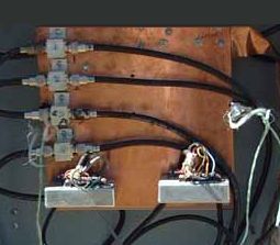
To achieve this you need to buy a copper plate (some use a copper pipe) large enough to lay down all your surge protectors, say at least 50x50 cm (1.6x1.6 ft) if your protectors are not numerous and not too large. I displayed at left one of the models sold by PolyPhaser, a US company represented worldwide. This plate comes with a fiberboard back and it suited to small to medium radio stations. Two copper straps 38 mm wide (1.5") and their accessories are also provided, the first to make the junction to the external grounding system, the second to bind the chassis ground of all your equipment. Of course for a large contest station you can bind several plates together or use a wider copper strap (up to 15 cm wide or 6" at PolyPhaser). We saw in the previous page that each of your equipment chassis had to be connected to the SPGP. To make this possible in a small station you can run a bus bar along the back of the station desk and connecting it to the SPGP second strap. The bus bar can be a piece of copper water pipe, a wide flat copper braid or, better, a copper strap too. The width of this strap should be between 30 and 80 mm (1-3"), the larger the best to keep the inductance as low as possible as the RF tends to travel on the outside of the conductor (the famous "skin effect"). As you hamshack will probably grow with years, think to buy an oversized SPGP. You will maybe install a second tower with its rotator in the future, get new gears powered on the main, new coaxial cables, etc. So instead or having to rearrange all these devices on a plate became too short, it is wiser to foresee now this expansion, and to leave some room left for an additional AC power protector, one or several coaxial protectors and maybe one more rotator or line shunt device. The alternative is to foresee now the place and connections for a second SPGP that will be linked to the first. Do not add protector for your input devices like the microphone, the key, the headphone or the mouse or any other device connected to a controller. Indeed these controllers, to name the transceiver or the computer are already grounded to the SPGP through the ground strap and the input devices will be automatically grounded to their chassis by design.
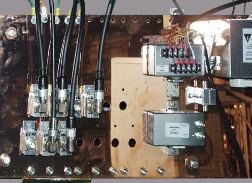
Last
but not least, it is time to mount your surge protectors on the
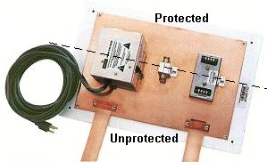
SPGP. Like on the above picture try to separate the protected side
of the SPGP (above center) from the unprotected one (below center).
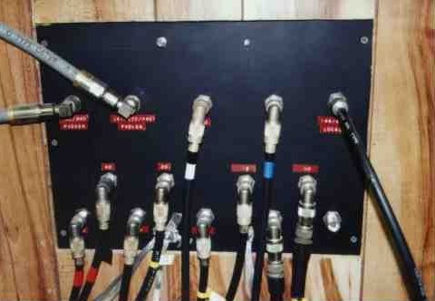
To accomplish this, coaxial protectors and most other devices are
provided with a label stating what side must be connected to the
"outside world" and which one must be connected to the
equipment. For example, on the coaxial protector is its labeled
"Antenna The spark-gap level
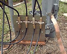
Security side, many installations create functional SPGP but they forget to respect some basic security rules. For example, in order that the SPGP works properly, you must maintain a physical separation of approximatively 50 cm (1.5 ft) between the unprotected cabling (rotator cable, antenna coax, incoming AC power, etc) and the protected wiring of the same connections. Why ? Because during the short time that the voltage flows through a in-line protector, there is a voltage difference when it crosses the input to the ouput side of the protector. At 66% of the velocity of light in using coaxials of low velocity factor, a duct 30 cm long (1 ft) is crossed in about 1.7 nanoseconds. In this short interval, any significant potential difference (if a device is not grounded for example) or inductance increasing can be a sink and thus experiment a lightning strike. This "spark-gap level" is established in respecting this separation of 50 cm. If you attach your cables well in-line, thus in opposite direction, you prevent this problem. In the same way, if you place the SPGP vertically, the thick cables like the coaxials will have, due to the gravity, a tendency to bend down and come close, and sometimes to touch the wire on the unprotected side of the plate. If this happens during the strike event, there is a chance for a spark-gap breach of the protectors between the cables, thus a failure of your protection plan. This rule can be somehow pushed if your tower is located a few hundreds meters from your house. Over 200 or 500m away for example, any strike will be dissipated to a large degree before it gets to the house. That has some effect in reducing voltage at the SPGP, allowing to attach all cables near each other. However the potential risk of an arc will remain. Remember Murphy's Law. How to attach the surge protectors on the SPGP ? Usually protectors come with a flange or a bulkhead mounting. This latter allows to easily screw the foot in L-shape to the panel. Depending on the thickness of the panel metal and the characteristics of the underlying support material (if any), it may be necessary or appropriate to drill a small pilot hole so that the machine screw does not buckle the surface or raise the panel from the backing material (what might happen using a fiberboard-backed copper panel). What is important here is that the protectors have a consistent, clean, flat, low impedance connection with the SPGP. If the panel is located in a non-controlled environment, say lock up in a box outdoor, then it may be appropriate to use a small amount of conductive grease or simply vaseline between the protector mounting bracket and the panel to ensure that moisture does not deteriorate the connection. When all devices are screwed or bolten in the SPGP, you still have to find a place in the hamshack to attach it, after which you can screw and plug all your cables and wires in their respective surge protectors. Ideally the SPGP should be placed within a few meters (1 to 10 ft) of the radio station equipment, inside of an external wall, close to a window or mounted in a full-fledged through-wall entrance panel. It should be placed between and inline with the entrance of the coax cables and the radio equipment. Assuming that it is in an controlled environment, there is no need to have a protective cover or box. Most amateurs mount the panel on the radio station wall midway between the coax entrance into the room and the operating desk. This helps to achieve a cable path layout that minimizes the potential to mix protected and unprotected cables. Creating the layout of the protectors on the panel will require some thought.
As displayed at left on the installation of Bill Otten, KC9CS, it is not necessary to protect your SPGP with a cover or to place it in a box. If it is well grounded and each of the chassis are connected to the panel, there are no safety issues or problems since no current must flow on its surface. If you place the SPGP outdoor with AC protectors, of course in this case you must place it under cover, i.e. inside an electrical weatherproof plastic box. Then take all your hamshack cables and plug them in their respective protected devices. From the outside do the same and connect all your unprotected wire on the other side of the SPGP. Attach also the ground wires of your chassis to the ground strap. If necessary label each connector or identify each pair with a colored strap if the protector is hidden. If the cables bend attach them with mini-clamps or straps to respect the spark-gap level. SPGP impedance Theoretically to prevent any energy sink, all devices and conductors must display the same electrical potential. As we have already told and will say again, if during a surge event the energy finds a path of lower impedance than another, be sure that it will follow that conductor to the end, what is maybe not the function of your ground system... So to be sure that your ground connection offers the lowest resistivity, all wires connections must run on the shortest distance, in straight line (with a minimum of bends in the wire) and as wide as possible, hence the utility of installing a wide copper strap to the outside instead of using a simple AWG wire, even of large diameter (at least #10 AWG). Due to its design this latter is inadequate to disperse the energy quickly and safely. The fact to run the copper strap ground from the SPGP in straight line to the external grounding system is easier to say that to do. Indeed, most of the time the environment forces you to divert from the straight line due to an obstruction, a wall, a door or even for esthetic considerations. So, knowing that, run the strap... as straight as possible to the outside ! Be only aware that no conductor like to be compressed, what modify its impedance, nor change of direction. In bending a conductor at 90° for example its inductance will increase of approximatively 0.15 mH on a distance less than 25 mm (1"). Repeated on a few meters this cumulative effect can significantly increase the transmission line inductance. Then, due to the nature of the fields components, a wide wire like a strap as a lower inductance per length, compared to a rounded conductor, and has minimal inductance for turns. The electromagnetic field doesn't like change direction neither. Each bend or turn represents a large change in the field orientation over short distance. If the change is large enough, some of the electrons traveling in the conductor can leave the wire and find by themsleves a path to the ground : there is an arc. Therefore if you desire that the grounding system works properly you need, here also, to respect the laws edicted by dame Nature. Whatever the size of the conducter, a wire has inductance. However larger is the wire size, lower is its inductance. Then to reduce the skin effect, the fact that the RF energy travels near the surface of the wire instead of using the central core, we should use oversized conductors to get the best path to the ground. That means that a railroad bar should be the best connector; it is massive and offers a large surface. Unfortunately this solution is not really conceivable as such a bar is first prohibitively expensive but also extremely heavy and cumbersome. So we need to find a cheaper solution but offering similar performances if possible.
To meet all these criteria at low cost but without impacting the security, there is a solution, and very easy to handle. It is using a copper strap in #26 AWG or 0.4 mm thick and at least 38 mm wide (1.5"). Displaying a lower inductance than the big #4/0 AWG cable (Ø16.4 mm), it is also much cheaper and lighter (14 kg/100m vs. 110 kg/100m). With its 38 mm wide, its cross sectional area is similar to the #6 AWG wire (Ø6.95 mm, over 9 kg/100m) and almost as light. If you install a Belden 9913 coaxial cable, its perimeter represents about 32 mm or 1.27" of incoming conductor surface. Our wide copper strap is still larger and its surface make it ideal for conducting the strike's RF energy to the ground. Of course, if you use 2 or more such coax, you can purchase a 10 cm wide (4") strap. For a 7/8" Hardline (Ø22 mm) a minimum strap width of 8 cm (3") is needed but 10 cm (4") would be better. If you work with three Hardlines, triple these numbers. It's no joking matter, dixit dame Nature ! To be sure to have the best path, inductance is calculated on the length of the connections between the SPGP and the ground, as well as on the number and sharpness of the turns. In practice this is the inductance of the coax cables between the antennas and the SPGP that you need to compare to the calculated inductance of the ground conductor. At last, to please dame Nature and present her a path of least resistivity, we need to offer a ground path larger than the total amount of coaxial surface area coming to the SPGP from the antennas. Why take the coaxials for reference ? Simply because since the most likely place for the surge current to originate is the antenna, and the coax cables represent a relatively low inductance connection to the surge, it is important that the connection to the earth ground be a more attractive (lower inductance) path than the path in any other direction. The other wires (AC, telephone, etc.) are small and inductive in comparison to the coaxial and can usually be ignored in figuring the width of the ground conductor. For that reason the use of a copper strap larger that the perimeter of all coaxials is recommended. We have now achieved our indoor installation. We have selected our surge protectors, learnt how to mount them of the ground plate to get a effective protection against the lightnings energy. Remain to bind this ground to the external ground system. Last chapter
|