|
|
|
All about Lightning protection
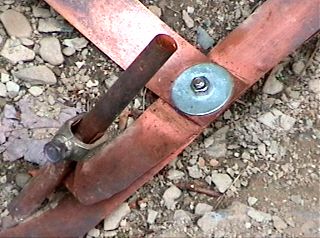
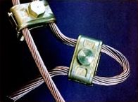
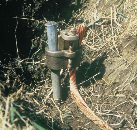
The external grounding system (IV) After have created our single point ground panel, SPGP, in the hamshack and attached on it our surge protectors as well as all cabling, take a look at the outside. We have now to develop a good external grounding system. Quite regularly we read on forums that an external grounding system can be made in burying simply a copper rod in the ground close to the hamshack. But if you read the other articles, you know how subtle can be the properties of the conductors and electromagnetic fields. I would like to know how a so light installation could be efficient in dispersing the energy of a lightning and its side effects, not to mention any voltage difference generated by a tower. I do not bet the least buck on this protection, inadequate to protect your radio equipments. Indeed, after have read this article, you know that an external efficient grounding system has for main purpose to dissipate the most lightning energy as possible before it finds the path to your amateur station... Good news, in the best ham installations, taking advantage of an extended estate, high conductive soil and of a lot of money, up to 90% of the lightning energy can be dissipated into the ground if it is properly installed. This is a high value that even some commercial sites do not reach ! However such results are hard to achieve for an amateur radio who is not necessary willing to spend more than $5000 in his lightning protection ! Ground radials and rods Let's take the case of your are a lucky amateur having assembled an antenna on top of tower placed close to your shack, knowing that a simpler installation will not require a protection as large as the one we are going to describe. As its name states, the external grouding system is... a system. That means that a ground rod is not a system ! To get an efficient energy dissipation and a good protection we need to create a newtork of interconnected rods and radials. It should be divided in several parts : - The perimeter ground - The ground radials - The rods From a pure electrical point of view there can be only one ground system for a facility (house or building). The fact of having more than one, separating for example the domestic from the radio ground, will permit current to flow between the different grounds and it will usually flow through your radio equipment since it will most likely be bridging multiple grounds. To get the best lightning energy dispersion, it is recommended to build the external grounding system as a thick network in shape of goose foot (X) away from the house, at both the tower base and the anchorage bases. All radials and perimeter ground lines use either a copper bare cable or, preferably, a wide copper strap (38 mm or 1.5" or larger). The strap is less inductive than #4/0 AWG cable and also less expensive. Ground rods should be as thick as a finger, 16 mm or 5/8" in diameter minimum, and 2.4m or 8 ft long, copper clad. Each ground rod should have a cylindrical shape, sharp angles providing area of potential arcs. You can also replace the rods by the ground steel frame that you 'd have sunk in the concrete base of your tower. At last a cheap solution, but that we do not recommend, should be to connect your copper strap to the grounded metal frame of a building or to the water-piping system, although an external duct is far more secure. All rods should have their connection with the copper strap exothermically bonded. Among the manufacturers supplying the molds and fusing material, in the U.S.A. name Erico, Inc and Alltec Corp. If you are not equipped for this operation, a locking system made of clamps could be used like lockers provided by Tyco Electronics.
To disperse as much lightning energy as possible we need first to bind the domestic and the shack/tower equipment grounds together creating a perimeter ground buried around the house and interconnecting the utility ground with the panel/tower ground. This perimeter ground solves two problems : it connects the otherwise separate utility and radio station grounds, and it minimizes the energy potential beneath the house so that the structure is not forced to carry some of the strike energy. Then you need to dissipate away the energy from the house and grounding your tower. To accomplish this, ideally the tower should be separated from the house by 6 to 15m (20-50 ft) minimum. For security reasons, if it can stand up independently of the house (selfstanding in the field or using guy-wires) the tower must be erected 1.5 times its height away from any housing or public infrastructure as explained on these pages dealing with this matter. The fact to move the tower away from the house reduces also the magnetic energy flowing in the tower that can couple with the wiring of the house. In addition you reduce the inductance of the coaxial line in limiting the surge energy heading towards your equipment. How to assembly the external grounding system ? You need a lot of cooper straps, rods and either large clamps or another means to connect the different parts together, good pliers and a hammer to drive rods (and useful to fight against Thor's hammer, Hi !).
From two opposite corners of the tubular base of your tower spread out a two set of 4 radials in X-shape as displayed at left. The radials length should be longer than 10 m without exceeding approximatively 24 m (80 ft), a value balancing the cost of installation vs. the benefit of a lower impedance system. However, if you are on a low conductive soil and if you experiment a too high ground impedance, in this case you can add more radials. Like using ground radials with vertical antennas, it is preferable to add more short radials than few long ones. If you have several towers or metallic housing within 30m (100 ft) of each other, interconnect their respective radial systems. Do not forget to ground each guy anchor to the ground system too (3 rods 50 cm long and 1 m of strap). Bind the central rod to the anchor or easier, to the guy wire just above the electrical insulators (above the turnbuckle for example) using a strap. Radials don't have to go in straight line; they can flow around obstacles but make turns as large as possible (30 cm or 12" radius minimum). The perimeter ground should go all around the house but some obstacles can be insurmontable (walkway, driveway, etc). In this case a 3/4 of perimeter going around the house is better than no perimeter ground.
Radials should be buried 15 to 45 cm deep (6-18") and connected to vertical copper rods. These rods should be spaced approximatively twice their lenght. For a rod 2.4 m long (8 ft), the space would be thus 4.8 m (16 ft). Thus if you install four 10m long radials at the base of your tower, you should have to drive 12 rods, 3 per radial, and bind them with clamps. If you cannot drive into the ground deeper than 30 cm (1 ft) or so due to rocks, drive short rods 30 cm long and place them closer, in respect with the twice-their-length rule, thus each 60 cm from each other. Being given that a rod display a cylindrical region of influence along its axis, placed too close, their respective influence begin to overlap and the capability of the ground rod to disperse the strike energy will diminished. Side effect, in trying to increase the number or rods you only increase the cost of your installation without derive advantages. If you drive a long rod into the ground, drill preferably the hole mechanically in order that the rod achieves a reasonnable "connection" to the earth. Back filling a hole manually should be avoided for the same reason. That said, there are a lot of things that influence the quantity and length of the radials like aesthetics, finances, property boundaries, vegetation, soil type, installation difficulties, to name just a few. PolyPhaser for example has a whole service dedicated to just measuring and doing the calculations appropriate to designing an effective ground system ! However the general recommendations are usually more than acceptable for an amateur radio station, both from an RF and safety perspectives. Tower and coaxial grounding To prevent you creating a specific external grounding system, and if you have not started yet construction of your tower, you should take advantage of the tower's connection with the earth as part of your external ground or Ufer ground. But be aware that if the Ufer ground is improperly constructed you do run the risk of exploding portions of the concrete ! This is to prevent such an accident that it is required that the pieces of RE-bars that constitute the framework be electrically connected to each other, whatever can write some radio amateur handbook on this subject. In our example this was accomplished by welding them to the horizontal steel loops. In addition, the anchor bolts must also be electrically connected to the RE-bars. This is a bit more difficult to accomplish since many manufacturers do not permit them to be welded due to the possibility of changing their mechanical strength. A simple mechanical clamp will work. As we told in tower assembling, in addition there must be at least 10 cm (4") of concrete left between the framework and the surrounding earth. At last, to keep the equipotential leveled, any radial coming within 1.2 m or so (4') from a metallic object (anchor, pole, fence, etc) must be bonded to this object to prevent arcing in a strike event. Check only that the metal properties are compatible when bonding the two objects.
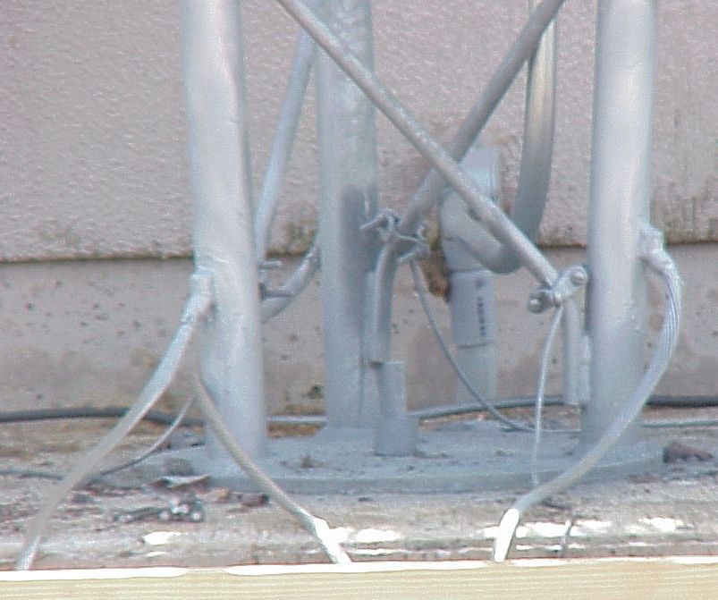
Without be informed, you will probably experiment some trouble trying to bind the ends of radials to your tower feet. Most steel towers are galvanized in plunging them in a bath of liquid zinc. This coating prevent the steel to oxidize. In binding the copper strap to legs with a clamp, you will erode the zinc, allowing the steel to oxidize and become rusty. With time, this will cause a change in the mechanical strenght of the tower and will modify its resistance. There is a risk that induring high winds exceeding 120 km/h (75 mph) during a dozen years the tower feets bend. You can prevent the steel to oxidize in inserting a layer of stainless steel between the zinc and the copper. Among other brands, Brite products will help you in protecting steel thanks to cold galvanizing, coating the metal with zinc to protect it from rusting. The coaxial running along the tower from the antenna radiator to the transceiver must also be grounded as shown in the previous drawing. The first grounded point is just at the top of the antenna, where the coaxial feeds the antenna. The second point is at the tower feed, just before it leaves the tower to the shack. The grounding point must be taken off as close to the base of the tower as possible. If you installed a very high tower, additional ground points must be taken off each 25 m or 75 ft as measured from the top. Due to the height of a tower, that can exceed 33 m or 100 ft at radio contest stations, there can have a voltage difference between the top and the base that exceeds 100 kV ! At 10% of that height, thus a bit higher than the height of a man, there are still 10% of that energy or 10 kV that can easily follow the coaxial cable to your shack. Therefore it is very important that this ground connection be established as close to the base as physically possible; 10 cm over the base is a good distance for our tower 33m high since we get a voltage difference of only 30V. For a 10m high (33 ft) tower, the take-off point can be at 30 cm high (1 ft) or so above the base. The grounding coaxial kit is different from a coaxial surge protector. This is totally other product. It can be purchased to any manufacturer of grounding kit. Don't forget to protect the interface with a weatherproof product. Like with anchors in connecting the ground kit to the tower be aware that dissimilar metals can corrode the steel of the tower. Coat them with appropriate products like the one sold by Anchor Guard. I will survive What about the lightest installations ? I am aware that not all amateurs have a tower in their garden. If this is of your concern, you will probably search for an external grounding system close to your house. But do not select any kind of support. Do not use neither the electrical system, nor the metal building skin, nor any pipe (metal cold water or stand pipe) to create your external ground. At worst use the building steel but even this framework is not the best RF ground and is highly inductive compared to a true external grounding system. The purpose of the lightning grouding system is to survivre to the lightning strike by ensuring that no current will flow to your equipment using the I/O wires and cabling system. This is mainly accomplished creating a single point ground panel to keep a same level of potential during a strike event independently of how the SPGP is grounded. Don't forget neither to leave the hamshack during the threaten of a thunderstorm if you installed a SPGP. Even if there is no current that flow between your equipements and on the SPGP, there are static because you are placed above the ground level compared to the external grounding system. If you take the risk to hold your metallic microphone in hand or to touch the chassis of a metallic gear during a strike event, for dame Nature you will be the object displaying the lowest impedance. During the strike event there is no doubt that the current vill flow through you from all protected devices, including the chassis of your transceiver to the ground.
Thunderstorms detectors being able to warn you when there is a lightning activity within 15 km around your radio station, it is better to leave the room as soon as you see or hear the thunder. As your equipment is grounded you can leave them powered-on. This is a practice that follow all radio broadcasters and equipements remotely operated like repeaters, which emitters and amplifiers cannot be switched off at each strike event. Of course like me you have probably heard many people telling that, although they were protected, they were stroke by a direct lightning strike, and more than once coming back via the ground path. Sometimes there was also either a coaxial or another device that was not protected... To reinforce your security, I suggest you to insert a second stage protection in placing surge protectors in each single outlet system as well as lightning controller in your main distribution panel. Artificial ground tuner At last, if you live in a building, accomplishing a good RF ground will be difficult at best. The good new, however, is that most installations do not necessarily require such a protection. If you have a well balanced antenna/feed line system, your installation is probably safe. If you erected a beam or a vertical antenna on the roof, then of course you need to protect your system. If you use a wire antenna and you have a relatively poor RF counterpoise or ground system, you might look into an "artificial ground", like the MFJ-931 tuner from MFJ Enterprises. This device can successfully resonate a random length ground wire and make the station "see" an effective counterpoise. At last advice. If you live in an appartment, make sure that your station is at least at DC ground (ground all the equipment chassis to a common point and then to a good DC ground) and keep the lightning ground outside the house. By way of conclusion There are some very important notions to remember : - One cannot suppress lightning - It is quasi impossible to build a system strong enough to compensate the effects of lightning. So our sole alternative is to search for solutions to reduce this risk (a direct strike or by induction) in applying the same rules than the ones used for plumbing : build a drain system to evacuate and dissipate the energy of lightning away from our electrical devices. The installation of such an electrical system or the modification of a lightning conductor should be made by skilled people or entrusted to a specialized enterprise, expert in HF installations. This work has to overhang all elements to protect. This is a very important subject, complex, which requests deep knowledges. If you are novice in this field, before investing in this equipment I suggest you to read several technical books about the subject, to follow maybe some courses, to question specialists and to plan on paper all your installation. If you consider that you can handle the project alone, if you are ready to invest the price requested in both time and money, go ahead, otherwise reduce your scope and phone maybe an expert. When your plan is achieved do ask an expert to check your project before beginning the real installation in the field. That is worth much more than hazards your incour in doing this work "at best", maybe without know-how, and see your hamshack be transformed in a sink and burn at the first strike event ! Take care. Good luck ! For more information about lightning protection
The essence of this article was published in 2002 in ARRL's QST magazine (June, July, August) and adapted for this website. I warmly thank Ron W. Block, KB2UYT for reviewed this new version and provided me additional explanations. Ron has been a distributor and consultant for PolyPhaser, a vendor of lightning protection systems, since 1989, and has completed The Lightning Protection Course by this company too. He is chairman of the Amateur Radio Station Grounding forum at the Dayton Hamvention, and published three depth articles on this subject.
|
||||||||||||||||||||||||||||||||||