|
|
|
Hardware Review
MFJ-1026 Deluxe Interference & Noise Canceler (II) Installation The MFJ being used while listening to
hams or broadcasts emissions, it must be placed near or above your RTX in order to
access controls and switches at the same time you read the RTX
S-meter and hear the result via the speakers or your headphones. How to install the unit ? This is not a mystery, the unit is placed between your RTX and the antenna and you can even add several units in serie in order to use the system as signal amplifier. 1°. First read the manual that gives
you all technical and practical information you need and especially
the fact to never install the MFJ on the ouput of either an
amplifier or antenna tuner but always just behind the RTX. If your
RTX has a built-in antenna tuner never uses the MFJ unless the SWR
reads 2 :1 or less. If you do, RF power and voltage limits of
the unit could be exceeded and damage its components. 2°. Check that the MFJ unit is switched
off and plug the power line to the outlet. 3°. Remove your lead from your RTX
Antenna input and connect it in the MFJ « MAIN ANTENNA »
PL-connector. 4°. Connect a short coaxial cable
with PL-connectors SO-239 between your RTX Antenna input and the
« RADIO » output jack of the MFJ. 5°. Connect the secondary antenna
working as the noise reference to the « AUXILIARY ANTENNA »
PL-connector of the MFJ. 6°. Switch on the PRE-AMP switch.
Depending the setting of two
jumpers (off by default) the unit will use or bypass the internal
whip. If it is not used (jumper 1 « on ») the system
will select the maximum amplifier gain. 7°. In the case of emission, connect
a shielded cable between the « T/R CONTROL » connector
of the MFJ and the « External PTT » output jack (or
auxiliary port) of your RTX. MFJEnterprises suggests to pull the T/R
CONTROL line LOW so the MFJ is put safely into the transmit mode,
before any signal is transmitted. 8°. Connect the MFJ ground (GRN) to
the station ground buss using a short ground wire constituted of
solid copper wire (not braided wire as this latter has a lower RF
resistance). Usually to improve the security the ground is located
at the place where the feedline enters the house and not on the RTX
itself). 9°. Connect the MFJ to its power
supply and switch it on. Operation If you don’t want to buy the
optional power supply from MFJ Enterprises you can use their plug and
pigtail to connect the unit to your RTX 12V DC Heavy Duty power
supply. The MFJ requires from 10 to 15 V DC and consumes less than
150 mA. Its RF emissions are negligeable and although the unit is
shielded you could hear a weak hiss in some conditions of work,
explained in the manuel. Once you plugged all your wires
and coax on the rear of the panel you are ready to set the front
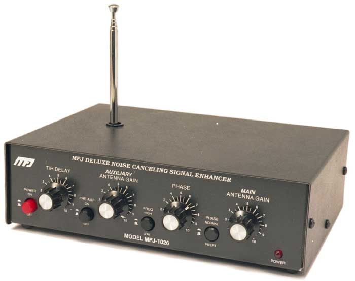
side. The front panel displays four
rehostats, four switches and the power LED. You will most than
probably work the most with the AUXILIARY ANTENNA GAIN that changes
the « noise » antenna gain, the FREQ HIGH/LOW switch to
select the frequencies group in use (3-7 MHz, 7-12 MHz, 12-30 MHz),
the PHASE that allows you to adjust the signal phase delay and the
MAIN ANTENNA GAIN that changes as expected the gain of the main
antenna.
First settings It is interesting to list the initial
procedure to cancel a steady signal to understand well that such a
device is far to be as easy to use as a DSP and that it requests
some manipulations and practice before to be used to work with it. 1°. Turn the T/R DELAY control
full clockwise in order to increase the recovery time (hang time) of
the internal bypass relay 2°. Switch off the unit (POWER
button out) 3°. Turn the AUXILIARY ANTENNA GAIN
controll fully counter-clowise (0) 4°. Select the right position for
the frequency switch FREQ HIGH/LOW 5°. Turn the MAIN ANTENNA GAIN
control fully clockwise 6°. Tune in a strong and steady
signal as fgar as possible 7°. Turn the POWER switch on. The
red LED lights. 8°. In the next seconds the MLF
internal relay will click. Look at your RTX S-meter and adjust the
MAIN ANTENNA GAIN counter-clockwise until the signal strength
decreases to its minimum. 9°. Adjust the AUXILIARY ANTENNA
GAIN control clockwise until the signal you hear from the AUXILIARY
antenna reaches the same or a level as high as possible as the MAIN
one, 10°. Readjust the MAIN ANTENNA GAIN
until see the S-meter change 11°. Adjust the PHASE control up to
hear a minimum signal in order it is cancelled. If the signal cannot
be nulled or increase change the position of the PHASE switch that
add (IN) or remove (OUT) 180° of additionnal phase delay. 12° Go back and forth between the
PHASE and GAIN controls until the noise is cancelled. This step
request some practice to « feel » how work the controls.
Once you will gain experience
with steady signals, try a peaking signal. Use only the PHASE
control and PHASE switch without adjusting the gain setting. Once you will be used to adjust the
differents controls on strong steady signals you could try to cancel
background noise and any other unwanted signal. In practice the MFJ perform
well at the condition to use it properly. That means that as far as
you can you have to determine what kind of noise you want to remove :
local or distant as for the first the AUXILIARY antenna has to
distinguish the RFI source much louder than the Q signal in order to
cancel it in perturbating the least as possible the desired signal.
This is rather a theoretical concept as in practice I think that
nobody knows really where do the noise come from, excepting when we
suspsect some devices inside the room and quickly identified. So on the good news, if you are
mainly concerned by local noise you are lucky as the MFJ does not
care of the antenna polarization nor the spacing between the two
antennas. On the contrary if you experiment
severe distance interferences it is suggested to respect a spacing
of 1/8l to 1/2l between the two antennas (a minimum
of 2 m or 6'), the
shortest the most consistent null you will get. But I cannot really
tell you what could be the potential problem as the fact to separate
both antennas by 2 m or placing them side by side along the wall of
my house gave similar results. You can also use the MFJ not
only to remove undesired noise but also to amplify the desired ones.
To achieve this objective, it is suggested to place both antennas
within 1l each another in the same
polarization if waves propagate via the ionosphere and preferably as
far from the local noise as possible. In the case one antenna receive
significantly noisier signal than the other, the best cancellation
is achieved when the MAIN ANTENNA receive the quiet signal and the
AUXILIARY the noisy one. If you cannot install the secundary
antenna, the telescopic built-in whip will do the trick nearly as
good. Polarization Signals captured by tilted longwires,
installed at 45° or in inverted-V, are also more difficult to
manage as they work in quasi crossed polarization, neither fully
horizontal neither fully vertical. As the secundary antenna is
rarely installed the same way – it runs more often horizontally
along the wall or it is tied outside to a nearby mast or tree -
noises are more difficult to cancel than signals captured by aerials
displaying the same polarization and direction. This difference in
polarization can even increase the fading when signals are not
locally emitted and propagate via the ionosphere. Therefore the MFJ manual reminds that
it is very important that the antennas are oriented in the same
direction and have the same basic polarization for best performance. Results in
the field As you understand the adjustment
procedure is quite complex but as all first hand taking you will
need some practice to be used in adjusting the controls. In the field signals are rarely
similar to cases studies. It seems that the MFJ gives poor results
with arrays antennas whatever say advertisings. In such a case the
MFJ is simply useless. But if you are working with wires
antenna, from longwires to multibands dipoles, or verticals, the
results are amazing. The noise cancellation requests however some dexterity as you have to adjust
simultaneously three controls : the two Antenna Gain controls
and the Phase control. But once you learnt how they are
interdependant, the procedure will looks easier. If you experienced severe power
lines noise from your house or even from 20 kV aerial power lines
located a few dozen meters away, the MFJ will be able to suppress
them (or nearly so) but at the two next condition : - first that the noise comes from a
specific direction and not from everywhere, - and second that you can also
provide to the auxiliary antenna a signal strength greather or equal
to the main one. The MFJ eliminates also very well all white noises emitted by battery chargers, transformers and other power supply you can have in the same room. I think also to the RFI emitted by computers, display, keyboard, mouse or when you move from one page to another on the screen while your RTX is switched on. In all those situations in which you can experienced strong noise up to S-9 due to direct waves the MFJ handles the QRM with ease and is able to null the noise up to below S-1 using just your aerial and the built-in whip ! Listen to a noise canceler in operation RFI caused by a PC switched On/Off in next room, by Chris Mackerell But the performances of this unit presents anyway some limits if you are not beware of them. If the auxiliary antenna receives a very weak signal that you cannot increase to balance with the main one for example, it will result a signal loss even worse than before processing ! When your RFI emitter is bearing exactly in the same direction as a DX station, the system will not be able to discriminate both signals and will suppress your DX too. This problem mainly occurs when your both antennas are e.g. installed 1/8 to 1/4 l apart with the same heading (parallel). To solve this problem try to place both antennas at right angle. As it is mandatory to provide to the
auxiliary antenna a signal as strong or stronger as the one received
by your main antenna, the whip is equipped with a pre-amp you can
activate. If it is still uneffective you have no other choice than
running a longwire across your room or outdoor to boost quite a lot the
concerned signal. Some amateurs also tested the PHASE invertor, a feature that allows you to amplify a signal in using two or more receive antenna and MFJ units. As the units will add the desired signal you can use this method to increasing much the signal-to-noise ratio of your DX stations. THis is another use of the unit too rarely experimented. For more information The MFJ-1026 (and MJF-1025) Deluxe Interference & Noise Canceler is sold by MFJ Enterprises and his network of worldwide dealers. The price list is $180 or 288 € charges and tax included if you order it in Europe. The product has been reviewed several times on eHam.Net as well as in a long article by G3GRO. FYI, the MFJ-1026 Deluxe Interference & Noise Canceler was originally reviewed in QST magazine, Apr 1998. Hope this helps.
|