|
|
|
The radio propagation Tropospheric traffic (VI) We leave now the ionosphere to go down to the troposphere, the region located below 11 km aloft at mid-latitudes where stands more than half of the mass of the Earth atmosphere. Following effects of temperature inversions (thermal inversion, highs), dense tropospheric layers, like airways, can guide VHF signals from one point to another, this is the "Tropo" traffic. You can easily anticipate its "activation" when a frontal system slowly moves over your area associated with a high pressure centered 500 or 1000 km away. Typical tropospheric paths are located about 1000 km in front of a cold front and 1000 km and more behind a warm front, and thus below and in front of a low pressure area or an occlusion. Hurricane and other large depressions lead to tropospheric ducting too.
This type of propagation in the most active in tropical areas and near large bodies of water where QSOs with stations located over 2500 km away are regularly worked. When exceptional conditions occur, contacts with antipodes have already been established in VHF on 6 and 2 m. Tropo ducting Another mode of tropospheric traffic is the ducting. Extended "tropo ducting" represents a super refraction in which the height and dielectric characteristics of the layer are so important at large scale that it offers true airways to VHF waves. These openings occur more often on 2 m than on 6 m and generally signals tend to be weaker and ranges not as great on 6 m as on 2 m. If the inversion begins already a few meters above ground the LUF (Lowest Usable Frequency) may be so high (over 1 GHz) that only UHF and SHF can be used. On 222 MHz and 432 MHz, contacts over 2000 km are not exceptional. The winter season has usually a cooling effect by nature and chokes off most tropospheric fun as well as the most enthusiastics hams. Like in Aurora traffic, to work with tropo it is preferable to use stacked directive antennas and to point a predetermined area in the sky with the hope that VHF waves can reflect and reach a remote station. This propagation is regularly used with the help of large cities (New York, London, Quebec, Paris, Brussels, etc) that act as landmark for the ham stations. Practically, both stations point an area over the city to increase the propability to make a QSO instead of pointing a random spot in the sky. For tropo ducting both transmitting and receiving antennas must be in the duct if amateurs whant to establish a QSO. The distinction between ducting and ordinary Tropo propagation is sometimes hard to draw. This mode of propagation is fantastic when tropospheric bending extends the range of stations well beyond their normal limit, but disadvantage, when the "Hepburn's Bending Index" is high ducting can cause unwanted interference from distant radio or TV stations too ! Tropo-scatter traffic We define this "TS" traffic the same way as the Tropo with this difference that here signals are scattered in a tropospheric area shared by two amateurss by the effects of temperature inversions and irregularities in the level of moisture, pressure, and maybe dusts of the atmosphere. Although it is difficult to recognize whether we are or not working on TS, in VHF this mode of traffic is open every days and keep its polarization. It is probably responsible for the majority of QSO on distances below 800 km. Microwaves From here we enter the 1 GHz band and up, a world that is only explored by advanced amateurs, often able to build their own equipement and software. This is not mandatory but that helps as there are few manufacturers providing antennas for these bands. Procom, sold by WiMo in Germany is one of them. You will find to this shop log periodics covering bands from 50 to 1300 MHz and dishes from 10 to 47 GHz. To read: The World above 1000 MHz, by G3PHO Rain scatter Traffic On hyper frequencies near 10 GHz during heavy showers or when it rains as cats and dogs, excited by the RF signals raindrops can reemit a part of the energy they absorbed during their excitation, allowing to work stations up to distances over 600 km. While it is unsecure to work in such conditions, mainly when a thunder is nearby, both stations have to bear their beam towards a common point where their signals will be scattered. You imagine well that hams working this way receive not only a highly distorted signal but signals perturbated by statics and QRN too. Therefore to avoid any misunderstanding they usually work in a more reliable mode as CW. Space communications Between 1-90 MHz the behavior of the ionosphere as mirror for the shortwaves is rather complex, with both reflexions and attenuations of the signal quite important. But the ionosphere is not completely opaque to HF waves. Like a window, when the incidence angle is very wide (wide compared to the normal), waves are completely reflected by the surface which acts like a mirror, while when waves travel perpendicular to its surface, they are able to entirely pass through it. But there is a cut-off frequency fp for the ionosphere beyond which it loses its capacity to reflect shortwaves. Depending on the latitude, the season and the solar activity mainly, during the day this frequency is around 3-10 MHz and goes down to about 2-6 MHz during the night, according to the next simplified formula, where Ne is the electronic density : fp (MHz) = 9 √Ne This frequency is valid for a HF signal radiated vertically. As soon as the incidence of the signal is tilted (what amateurs seek to reach DX stations) the frequency increases proportionally with (1/cosθ), θ representing the incidence angle with the normal. As we saw about the skip distance, it is also known as the obliquity factor Q. So, if the signal is emitted at 45°, the cut-off frequency of 10 MHz goes up to 14 MHz, etc.
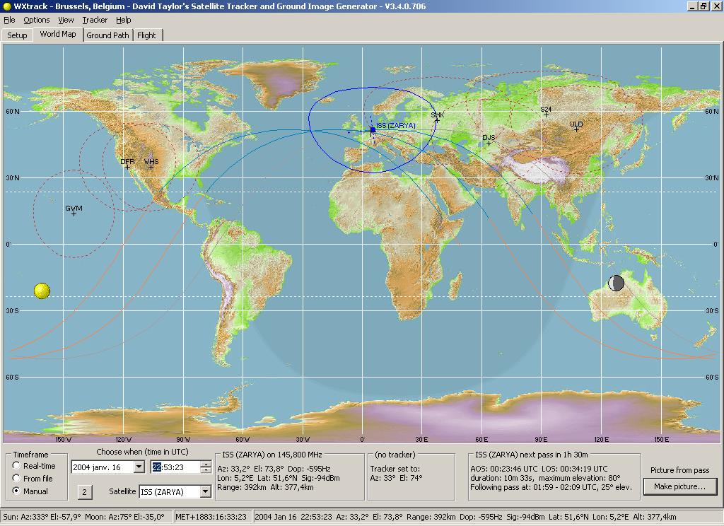
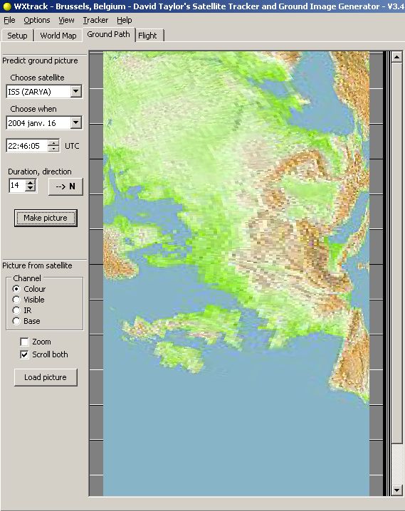
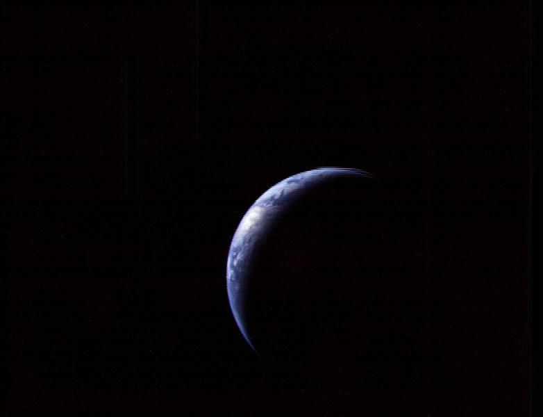
Extrapolating these properties towards higher frequencies one notes that signals emitted in V/UHF and SHF bands (S-, X- and K-bands) easily pass through the ionosphere, except at grazing incidences on the lower frequencies (when cosθ is very small). Usual the maximum distance of radio communications are limited by the Earth curvature and propagation conditions in the atmosphere or the ionosphere. Communications over the horizon usually require more power and a directional antenna. In using satellites we are neither limited by the properties of the ionophere nor the Earth curvature but rather by the "circle of visibility" like the one traced in blue on the tracking graph displayed above. The signal path being predictible, a tracking software can easily show you in real time the position of any satellite and help you scheduling a QSO. The duration of a typical communication by satellite can exceed 15 minutes (e.g. with ISS orbiting at 380 km of altitude), in fact up to the satellite is out of range, over 3000 km away from your station. It all depends, of course, on whether the satellite is orbiting on a low or highly elliptical orbit and on the power and gain of the antenna system.
Amateur space communications are mainly performed on V/UHF and higher frequencies. They are divided in two main categories : communications with artificial satellites and via the Moon, the famous EME. Radio amateurs are using OSCAR satellites (Orbiting Satellite Carrying Amateur Radio), most orbiting at high altitudes between 400 and 1500 km above ground (Phase III) and soon on the geostationary orbit (Phase IV). AO-40 was one of the rare satellite to be placed on a Molniya-like elliptical, inclined orbit ranging between 810 and about 59000 km.
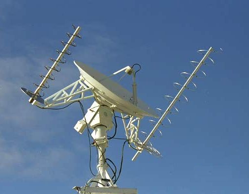
A typical satellite communication works in full-duplex mode (that allows the emitter to hear his own signals in real time as well as those of the calling stations) using a transponder (that allows to relay signals on different frequencies). The satellite transmits on one band (downlink) and receives on another one (uplink). If most use the same band of frequency to emit and receive (like ISS on 145.200/145.800 MHz), many OSCAR and RS (Radiosputnik) satellites work in two different bands (e.g. Mode-A : 145 MHz uplink, 29.300 MHz downlink, Mode-B : 145 MHz uplink, 435 MHz downlink; Mode-L : 1269 MHz uplink, 435 MHz downlink, etc), hence sometimes the necessity to use a receiver/transmitter converter called a transverter. Due to the movement of the orbiting satellite, the polarization alignment of the antennas are very hard to maintain. If we used an ordinary beam or a vertical antenna the loss could exceed 20 dB. Therefore, to not loose the signal due to a rotation of the polarization plan, antennas for space communications use a circular polarization; antennas show elements arranged in form of an helix or a spring (6-turn helical antenna for VHF, 8-turn antenna for UHF) or amateurs use a cross-Yagi (using between 10 and 25 elements). In this way ground antennas are no more sensitive to polarization motions of the spacecraft antenna and communications become much more comfortable.
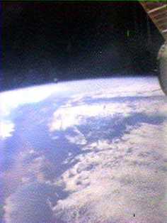
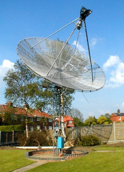
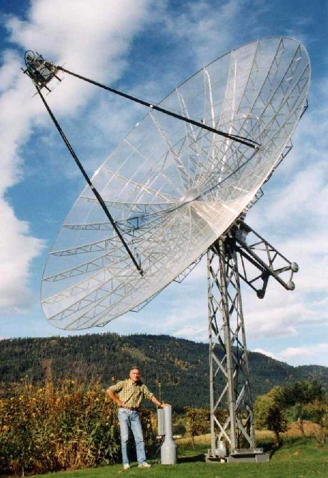
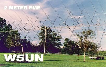
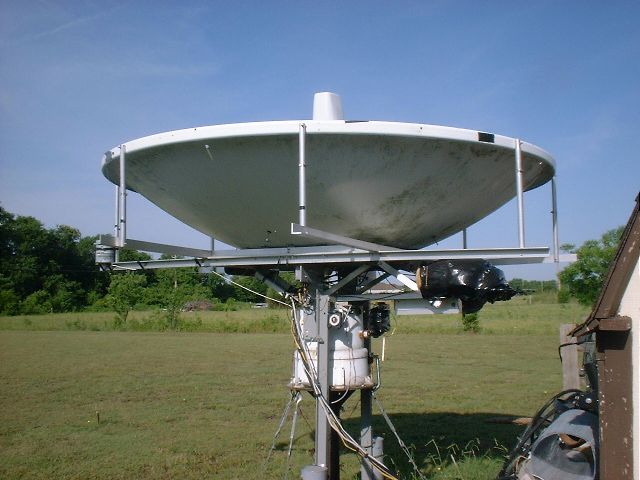
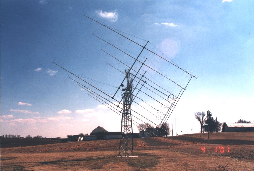
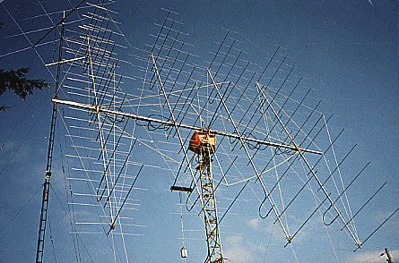
However, most satellites including OSCARs operate on the downlink at very weak power level, up to reach only 4-5 dB over the background noise. Associated to atmospheric noise at daytime, receiver noise and a poor rejection of strong nearby signals (e.g. near FM emitters), a communication on the VHF bands can sometimes be difficult, mainly in B-Mode. Therefore, you will never find a satellite installation without preamplifier nearby. A low-noise preamplification is essential to receive downlink signals. Working on microwaves, at frequencies of about 2401 MHz (13 cm), a satellite antenna must also be placed as close to the radio as possible to avoid losses in the feed line. It is therefore not surprising to see most amateurs using the famous low-loss coaxial cable Belden 9913 or even a Hardline to feed their antenna. Like any station, a station satellite is usually completed with an antenna rotator, its associated control box, a S-band SWR-meter and a good tracking software. To work on the highest frequencies the usual beam or vertical is often replaced with a dish antenna. At last, space communications include not only the usual modes like FM or SSB, but you can also take advantage of packet radio transmission and SSTV, mainly with the ISS crew. In this case a lighter installation can already give excellent results as the picture free of QRM displayed at left demonstrates with a SSTV image received from MIR on 145.985 MHz FM by Kevin D. Kinkade, KE6BLQ. The ultimate DX, the EME traffic EME stands for Earth-Moon-Earth and in this very special activity the Moon can be used as a passive reflector ! This traffic is sometimes considered as an achievement by some amateurs who called this activity the "ultimate DX" as this kind of traffic requests usually very directional aerials using several tens of elements repeated from two to a dozen times and which inclination above the horizon is sometimes controlled by computer (Altazimutal mode). At microwaves (1-47 GHz) some advanced amateurs do not hesitate to use dish antennas like G4CCH, VK3UM or F2TU's home-maded installations displayed below. Up to date the most powerful station is W5UN, living in Texas, who works in all frequencies between 144 MHz and 24 GHz and who is even able to capture QRP-like stations using powers under 100 W. In this very exciting mode there is only one simple thing, the procedure : you send your message to the Moon with the hope that it will be heard some hundreds or thousands kilometers away by your correspondent who can be G4CCH, whose dish is display at right ! W5UN's EME pages - VK3UM's EME software
But behind this simple action, the performance is far to be so simple. A few examples. First the Moon must be very low above the horizon in order to reach a DX station. So 5° is a good elevation but as the Moon moves in the sky, its position above the horizon shift a few degrees and thus force you to steer your beam each day to other coordinates. Therefore computer assisted aerials fixed on altazimutal mounts are very appreciated. But other problems are to come. Knowing that the Moon is at about 384000 km away from the Earth (so 760000 km go and back) and it reflects only 7% of the energy received by the Earth, the receive signal is about 200 times weaker than the one transmitted; it is subject to a loss between 242 and 296 dB depending on the frequency ! Signals are also regularly lost in the ionosphere due either to the faraday effect (a phase rotation between 50-1296 MHz), a change in the spatial polarization between the emitter and the receiver, the Doppler effect as both celestial bodies are in movements (350 Hz shift on 144 MHz) or due to QSB induced by the Moon libration. So you have more chance to loose your signal than to hear a DX station... very very very weakly and often noisy. Therefore the use of a spectrum analyzer is very appreciated (e.g. Spectrum Laboratory, Sky Sweeper, etc). Good to know, in EME, like in any other mode, contests are also planned all along the year. An EME station can already be set on 144 MHz. This is probably the easiest way to begin in this fascinating activity. It can be completely assembled using commercial products, stacking for example 2 or 4 cross-Yagis or helix antennas in order to get a gain over 18 dBd and a beamwidth of about 15°. However, according to Mike Cook, AF9Y, knowing the price of current commercial products, a better opportunity can be met on 435 MHz using a 200 W transmitter output, a pair of low cost cross-polarized Yagis (3m or 10 ft long) offering a 15 dB processing gain over a typical CW waveform and a receiver offering a 0.5 dB noise figure. But for serious EME enthousiastics this is not enough because such an installation offers only a little more than 50% chance to succeed an EME contact... Indeed, the return signal being very weak, the system should also offer the lowest noise temperature in order to reduce noise coming from cosmic sources, the thermal noise radiated by the Earth and RFI. Then you will need of a good low noise preamplifier (GaAsFET with a noise figure of about 0.35 dB or 24K), a powerful VHF amplifier, a good DSP software and a Moon tracking software. As alternate you can also work on 432 MHz where antennas are relatively smaller but you will experiment practically the same technical problems. As in VHF for example, you cannot use metal masts, and frames in line with the Yagi elements or the feed lines and other devices become also harder to design to prevent adverse effects on performances of your antenna system. We cannot hide this fact, a microwave EME station is expensive and requires skills if you want to work on the highest microwaves bands up to 24 GHz which require dedicated hardware and a lot of know-how. Clic on the next link to see some extraordinary EME ham shacks and the type of antennas they use... bigger, that doesn't exist ! HB9BBD's EME pages and Audio files
This activity is so prestigious that EME QSOs are regulary scheduled in CW in the first 30 kHz of the 2 m band. There are also EME voice signals around 144.115 MHz but more rarely. On 432 MHz the EME calling frequency is 432.010 MHz in CW and 432.015 MHz in SSB. To convince you participating in EME activities, if you live in the U.S.A. meet on Saturday's and Sunday's on 144.345 MHz at 16:00 UTC during summer daylight savings time, and 17:00 UTC at other times. You are welcome on this net. Schedules and EME operating information is exchanged on this net. You can also exchange information about EME using OSCAR satellites in Mode-B (downlink at 145.950 MHz) and Mode JL (downlink at 435.975 MHz). With some chance you could even contact some monster EME stations like the radiotelescope of Arecibo, aka KP4I/KP4EOR (305 m, contacts with the USA only), WA6LET at Stanford Research University (50 m), W8IWI/8 at Green Bank (42 m) or VE3ONT (46 m), the Algonquin Radio Observatory used by the Toronto VHF Society. In Europe and Asia there are also some amateurs seriously involved in EME. Shall you be the next EME contester ? For more information Propagation analysis and prediction program (on this site) Satellites reception (on this site) Space Communication with Mars (on this site) An Introduction to HF propagation and the Ionosphere, ZL1BPU Radar Systems on Shortwave (OTH radar), IARU, 2013 Your Guide to Propagation, RSGB The New Shortwave Propagation Handbook, CQ Radio Propagation - Principles and Practices, RSGB ON4UN's Low-Band DXing, ARRL The VHF/UHF DX Book, RSGB VHF/UHF Handbook, RSGB ARRL HANDBOOK for the radio amateur, ARRL Radio Amateur Guide to the ionosphere, Leo F.McNamara, Krieger Publishing Company, 1994, Amazon Propagation Studies, RSGB IPS Introduction to HF Radio Propagation, IPS Dynamic Ionograms for the USA, NGDC Dynamic Ionograms from the world, ULCAR or IPS UKSMG (50 MHz) HF-Fax (info and live cams)
|
||||||||||||||||||||||||||||||||||||||||||||||||||


