|
|
|
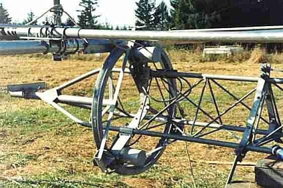
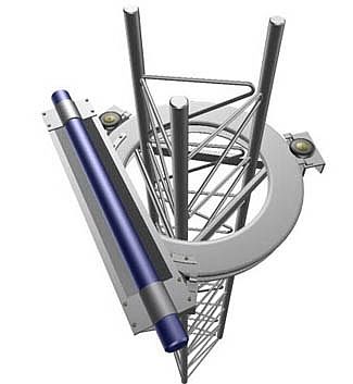
Select your antenna rotating system Turn, turn, turn It sounds like "R-r-r-r-r" while rotating although in the reality it is really a silent gear. But I use this judicious subterfuge to divide the selection of a rotator in several "R-points". We will mainly discuss about the rotator supporting an antenna mast. There are other solutions to turn an antenna like the rotating ring equipped with a TIC ringrotor.
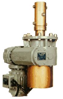
R as Rotator In selecting a directive antenna, we cannot forget its inavoidable rotating system. The main role of a rotator is to... turn the antenna at 360° and, optionally, to support the weight of the antenna and the one of the supporting mast, nothing more. If it smokes or grates this is a bad sign ! A rotator is usually silent and let you operate trouble-free.
The rotator is as important if not more as your antenna insofar as this is a mechanical accessory, subject to load (overload), rotation, torque, vibrations, temperature and moisture changes, when it is not stroke by a lightning. Its robustness and reliability are essential, all the more when it is attached 10 m (30') high and maybe hard to access; you should have to place it there and forget it ! Rotators come in several grades from the light duty TV rotator of 5 kg (10 lbs.) suited to turn a light antenna not greater than a V/UHF Yagi to the highest duty rotator of 50 kg (100 lbs.) or more able to drive stacked multi-band Yagis made of stainless steel. To be complete we must add the electric stepper-motor suit to turn full-length Yagis on the low bands, and for the anecdote the propeller-blade pitch motor associated to its fuel tank able to turn all you want, Hi ! Note howeve that TV rotators are designed to aim... TV antennas, no ham antennas. That means that the low-end TV rotators lack of braking and holding capabilities. An antenna is not a weather vane (or it shouldn't really) but under high winds exceeding their inertia force, it will turn endless in its ball bearing, in direct or reverse direction, what sometimes can break gears. So, always select a TV rotator including a braking system. Most of these light duty rotators are able to aim a 3-band 3-element HF beam made of stainless steel, but not an heavier charge. At last, if you work with a beam which weight is neither very light nor really heavy, but at the limit to be transportable, instead of purchasing a light and cheap rotator thinking to make a good deal, it should be a pity having to replace it after have experimented some troubles. Thus, a good advice, select immediately a higher model, more robust, offering a safety margin. It will be probably twice as expensive as the previous but you will probably keep it for ever if you take care of it (engineering side in reducing strains on bearings, in not using the beam like a weather vane for example or turning it too quickly by the cooldest temperatures). Be aware however that a rotator will surely answer with softness to your commands but inside well-defined specifications. R as Requirements Several points must be highlighted when selecting a rotator system. Among the first things to check, know what you want to do with your rotator system : do you need to move your antenna in elevation or only in azimuth ? Do you want to track satellites or aurora when they are high in the sky or you never work in this way ? Then do you want to drive your system automatically, by software or manually ? Answering to this questions will affect the choice of your antenna control unit (analog, digital) and the one of the optional interface (linking your control unit to your computer) and the related software (setup and tracking software). Tracking in 2D or 3D In matter of rotating system, requirements on VHF can be rather different from the needs of a HF operator. If you are interested in working by satellite for example or in Aurora, MS, Tropo and other EME activity, you need a rotating system able to aim your V/UHF antenna in 3D, I mean in the two planes. You must thus control the azimuth and the elevation angles. To operate on "steady" weather events that always stay or evolve in the same quadrant of the sky within a few degrees, you can aim your antenna in 2 steps, moving first the azimuthal axis, then raising the elevation axis on your target. A cheap solution is to entrust this function to 2 light TV rotators, one attached on the elevation axis the other on the azimuth axis. Of course this system must be associated to its indispensable control box. But in using two independent rotators the tracking is neither as fast nor as accurate as using simultaneously both rotators, their move being controlled by an interface card installed in a computer. This will be mandatory to operate with ham satellites like OA's, OSCAR Phase III's or to receive images transmitted by weather satellites like NOAA's emitting at 137 MHz. Indeed, these satellites are placed on polar orbits highly inclinated over the equator and cross thus high in the sky at a speed reaching 18° per minute, equivalent to 4 times the width of your fist, arm tight. Knowing that a 20-element V/UHF beam shows an half-power bandwitdth of about 25° and up to 20° with 30 elements, you will need to aim your antenna beam with an accuracy within 20° or about one minute time. Of course it is always possible, and a lot of hams work this way, to use a ground plan antenna to work by satellites, including packet radio with ISS. If you want to control both axis of your antenna simultaneously, the best configuration is using e.g. a Yaesu G-5500 rotator ($600) with its computer interface ($500) and the satellite tracking software NOVA for Windows ($60). But this solution is rather expensive when we know that you can build yourself the interface for a fraction of its cost. For your information the September 2005 issue of QST published such a building, an article signed by Mark Spencer, WA8SME.
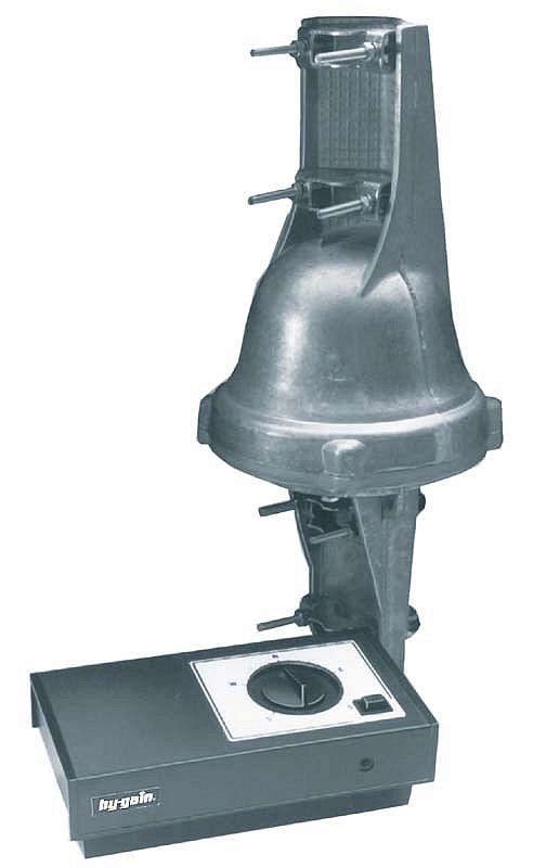
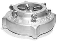
Although the Moon and some ham satellites travel usually high in the sky, there are two alternatives to track them at low cost. First many amateurs content with using only one rotator, working mainly when the Moon is close to the horizon. This is also the case for satellites orbiting on low orbits like the old family of OSCAR Phase II's. By 50° of latitude they move a dozen degrees over the horizon, just above trees. A single light duty rotator like the famous Hy-Gain AR-40 ($270) displayed at right is suited to this job and is even able to support light stacked beams. You will find it in "all good ham shops". The other alternative is using an old motorized german equatorial mount or an altazimutal mount equipped with a Goto system like the one used in astronomy, the Yagi replacing the scope. However this solution is more expensive than a light duty rotator; moreover the keplerian elements of ham satellites are not at all or not all included in the built-in databases of objects that the system can automatically track. In all cases, as soon as you use a rotator, plan to have two or several cables to run to your shack : the antenna feed line and the rotator coax. If you work on V/UHF bands, add on the tower, near the antenna, the essential low-noise preamplifier showing a typical noise figures of about 0.5 dB. Your feed line must thus be of the best quality to show the same losses or almost. Therefore on V/UHF, if you antenna is placed over a few meters away from your transceiver you must replace your ordinary feed line by a very low loss line showing an attenuation less than 2 dB per 30m (100 ft). Belden 9913 and low impedance "Hardlines" respect this value and are waterproofed.You will find these accessories to all dealers of ham and satellite equipements. At last don't forget that all this material excepting the rotator, what includes the preamplifier, the optional converter, the filters, the additional relay, and the power supply are not weatherproofed. They must be encased in a waterproof box at the base of the tower or the antenna, like should be the junction between your feed line and your coaxial connector (PL-259 and SO-239 plugs are not weatherproof). Taken as a whole a VHF installation might look complex for a HF operator not suited to work on upper bands. However, taken individually, device per device, cable per cable, such an installation is easy to setup. In the worse case, do not hesitate to contact your radio club or a near friend working in these modes to help you. Rotator Comparison Table
Digital control units If rotators are controlled via an external control unit (Alfaspid, CATS, Hy-gain, Prosistel, Yaesu, etc) the new generation of rotators take advantage of computing and support logger programs like CTWIN, Writelog, LOGic7, etc. What to think about these interfaces driven by computer ? Here is a short review. In the case of Prosistel model PST-641D ($794), the rotator setup is always controlled from an external digital controller PST-2051D ($995) but operations can be customized using a software running on your computer. In this case Prositel provides a complete software that controls the rotator speed using pulsewidth modulation. Yaesu G-800DXA rotator ($430) comes with a GS-232B interface ($570) driven via the Windows Hyperterminal program, like the one sold by CATS (rotator RD-180, $700; DPU-1800-D controller, $399) or Hy-gain HAM-V ($950 with DCU-1 controller). AlfaSpid rotator ($876 for the rotator and controller plus $35 for the azimuth mouse) also supports logger software but some bugs seems constraint the controller to only run in Yaesu or Hy-gain emulation mode. All these solutions are expensive, with prices without computer starting at about $900 to reach $1800. If the interface still worked correctly, even setting parameters manually (e.g. not using default values) that should be fine, but it is not always the case. Some controller refuse to communicate with Windows Hyperterminal or in their native mode and only accept the Yaesu emulation mode. So up to now, in my humble opinion, the computer control of rotators is not yet mastered and I warmly suggest you to only use an analog external control unit. Of course using a manual system, you will have to push on some buttons to rotate your antenna. But even working with an automatic system, you have to wait some tens of seconds until your antenna is in position before to work again. The digital interface could be a plus, but in the hands of a novice or a casual amateur it can be frustrating to not be able to communicate with the system, all the more that these digital units show sometimes hardware failures and bugs. So keep your money and invest in something more reliable and useful than a digital controller. R as Robust For the large and heavy beams, say from 4 elements made of stainless steel (> 20 kg or 40 lbs.) a high quality heavy duty rotator is warmly recommended. But to understand this choice, we have to explain what are the strains than must support a rotator through some advice extracted here and there from field experiences.
To improve the longevity of your rotator you must know that the torque, flexing, moment, misalignment and wind load are maximum on top of a tower, at the junction between the mast and the antenna boom. On the contrary a few meter below most of these constraints are either absorbed or much reduced by the tower structure, all the more when is it free-standing where the tower really "lives" and reacts according strains applied on its structure. It is thus recommended to install the rotator as low as possible inside the tower, preferably 3m below the top, what will also lower its gravity center. You can also install the rotator straight at the base of the tower with the advantage to be easily accessible for installation and service. In this case the central mast must be longer than the tower and kept in position with accuracy, what can be quite hard to achieve if the tower does not have intermediate horizontal plates to circle the mast. Placing the rotator several meters below the top is also interesting at starting and stopping of the rotator because by high winds the gears will have to bring out the most of the torque to rotate the mast. Then, the lower is the rotator the less significant are the effects of a misalignment on it. Therefore a "depth" of 3m inside the tower is not a superfluous distance to install the rotator. A misalignment is usually caused by loose U-bolts or loosy fixings between the mast and the rotator grip or between the mast and the antenna boom. Several situations occur : some amateurs use undersized masts that are sometimes not dead-center mounted in the rotator. Others avoid to tight bolts too much thinking that it is a wise precaution during bad weather to allow some slippage in coupling to prevent serious damage in casting. In fact a misalignment has only drawbacks, in slipping the mast in the grip instead of turning the antenna. By high winds an installation so sloppy has for the sole consequence to bind or break a casting or more surely to burn out the rotator (overdrived) or its motherboard. In that matter it is advisable to place a large tubing on top of the tower through which the mast will protrude, in order that the tubing supports the lateral forces instead of the rotator casting and thus the mast. R like Reinforced We all known that fixings attached at two points along a mast are better than one. But we also imagine easily than the point located just above this fixing is a weak point, subject to bending under hight laterial tension. By windy weather or when there is ice of the antenna elements (or both in winter), the wind load area of a large beam mounted in-tower can exceed 1m2 (~12 sq.ft), generating a strong lateral force on the rotating axis and damage the weakest gearings. If the weight and the strain supported by the rotator are too important, over 100 kg (200 lbs.), under these circumstances you have chance to overload the rotator and burn its system.
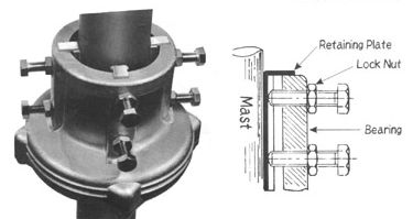
You can lighten this weight and this strain in installing a thrust bearing on top of the tower, 3 m higher or so above the rotator. It will be welcome to hold all the load, leaving to the rotator the only task to turn the antenna. Like the rotator, is must be installed on a platform. To prevent any trouble like the dropping of the mast on the rotator if the thrust bearing becomes loose (although the height of this drop is reduced to some centimeters, a few inches, the total weight of the antenna and the mast can exceed 100 kg or 200 lbs), as a security backup it is recommended to place above and close to the thrust bearing a reinforced sleeve (a tubing) 50 cm high (20") or more, adjusted to the mast diameter through which, and as high as possible, you pass perpendicar to the mast a heavy bolt that will prevent the upper part of the mast of falling on the rotator. If the sleeve is fit closely around the mast, sealed with Silicone Caulk, it will strenghten it, reducing the chance for the mast to fold at the bearing. But still more important, placed farther up the mast, well away above the thrust bearing, it will also reduce the bending stress that exists in the area of maximum momentum that is located between the rotator and the thrust bearing attachment. This solution applies the basic rules of structural engineering[1]. R as Reliable To rotate a HF antenna, sometimes massive and offering a large inertia, you need a rotator at which applies all superlatives. The strongest rotators support masts up to 53 mm diameter (2-1/16"). To support potential high torques generated by high winds and large momentum using long Yagis, high-end rotators show an effective moment up to 2000 m/kg (3400 ft/lbs.) and are able to support a wind load up to 3m2 (~34 sq.ft) at variable speed. Most use an alloy ring gear that gives a strength up to 6804 atm or 6894 bar (100,000 PSI). To get the best accuracy, bearings are 10 cm diameter (4"), are doubled or tripled (ball bearings are place on several concentric rings), using up to138 ball bearings. They are associated to either a disk brake system or an electric locking steel wedge brake mandatory to prevent the mast to rotate freely. Some models are also protected against RF currents thanks to ferrite bears. The most reliable work with special grease supporting temperature up to -34°C (-30°F) and all models are of course weatherproofed. At last, the control box that you will place on your desk is front illuminated in mid and high-ends models, the rotation being started/stopped by pushing on a switch. A brake switch is also available on most models. R as Ready At last you have to install your rotator : either at the base of the tower or about 3m below the top. Place on top that means that you must use a tubing of about 4m high and between 40-50 mm diameter (1.6"-2"). It can be telescopic if it is sturdy enough to support the load of the antenna. Often towers provide a few meters below the top a small plateform on which you can easily place the rotator and an opening on top to insert the mast. Then, when the antenna and the rotator are installed, well aligned, tight and bolten, you have still to check the grounding. When done, connect the rotator input plug to the cable running to your control unit. Switch it on, you are ready ! Do not forget than once installed, if one day you need to repair your rotator or the antenna, you should have to climb on your tower... But maybe not if you intelligently installed your rotator and antenna in a system that you can lower or tilt for servicing, a subject that we are going presently to review next to other features specific to the assembling of an antenna system. To read: Assembling your antenna system
|
|||||||||||||||||||||||||||||||


