|
|
|
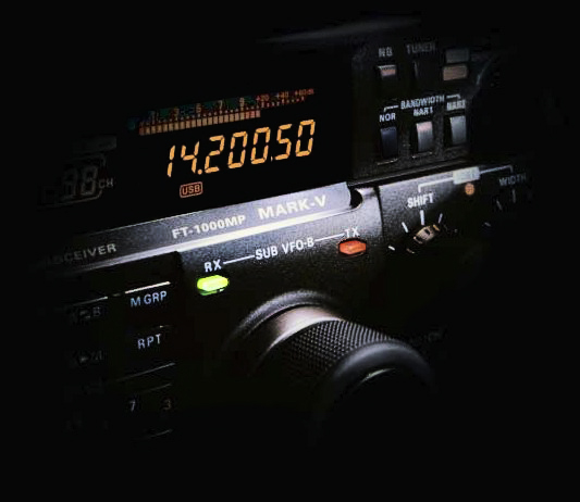
The Yaesu FT-1000MP Mark-V transceiver
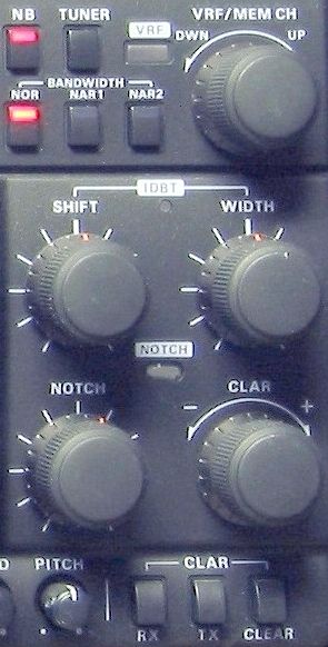
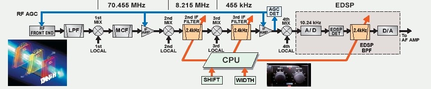
The Yaesu war plan against RFI (II) The Yaesu FT-1000MP Mark-V provides a cascade of filters to remove interferences. Their technique looks like a war plan drawed up against RFI. Yaesu defined himself his countermeasures as a "interference-fighting system". Indeed, from the HF stage to the AF stage, the Mark-V provides no less than a ten of filters, without speaking of EDSP, to cut interferences at feet before they reach the speaker. Here is the list of all filters at your disposal that we will review in more detail later : - VRF : this is a narrow passband filter located in the HF circuit of the receiver (see shuttle jog dial below) - AMP, IPO and ATT : select of an entry stage to optimize the signal in conditions of QRM - AGC : the automatic gain control can be set to work in automatic mode or manually, Fast (SSB, CW) or Slow (AM) - RF gain : turned anticlockwise it helps to clarify a weak signal as it enters the first mixer - Noise Blanker (NB) : to remove short pulses and transcient QRM (from near engine, power lines, etc). Can be customized using Menu 2-8. - RFI filters : two filters banks can be selected for the second IF at 8.215 MHz and third IF at 455 kHz, even in cascade. You can also select the suited bandwidth in pressing one of the BANDWIDTH buttons located at the right of the display : NOR, NAR1, and NAR2. Note that the filter you want assign to each hutton can be set via the Menu
- SHIFT control : linked to IF filters too, it change the IF bandwidth according to the working frequency in all modes but FM - WIDTH control : linked to IF filters, it helps in reducing the bandwidth in presence of QRM Note about WIDTH/SHIFT. In presence of QRM on both sides of a frequency, SHIFT and WIDTH help you remove QRM on both wings of your working frequency, leaving your QSO free of QRM. Begin by removing the QRM using SHIFT on one side of your frequency, then use WIDTH to remove the QRM on the other side. Once you are used to play with the IDBT on the Shuttle jog, you will discover that it becomes easy and fast to shift automatically the IF filter bandwidth according to the SHIFT control setting.
The turning step of SHIFT/WIDTH is set to 10 Hz by default. Using Menu 1-2 (SFt-StEP) you can increase the step up to 20 Hz if needed. - Manual NOTCH Filter : this is a very useful filter that is not always included on mid-range transceivers for some obscure reason. It is indeed as useful as a the noise reduction or the AGC. The NOTCH shows a profile in V-shape that helps to suppress an undesired carrier, voluntary tunes or a CW station placed just on your working frequency and that disturbs your working conditions. Press this control knob and turn it slowly until the signal is removed. If the tune is over 1.2 kHz from your receive frequency the NOTCH can be useless. In this case there is another solution. Disable the NOTCH and readjust the WIDTH and SHIFT controls to place the boring carrier out of your bandwidth. The NOTCH function is also associated to three operating modes through Menu option 2-9 (NotcH) : IF NOTCH, DSP NOTCH (Auto DSP) or both (SELECT). This last selection using the DSP will remove any residual interference that might pass through the IF stage. The shuttle jog dial One of the main difference with the FT-1000 is the new shuttle jog dial associated to the main VFO knob. By default the frequency increment step is 10 Hz.
By pressing on the shuttle jog dial, to the left or to the right, you increase or reduce the increment of a few steps and, more or less quickly depending on whether you turn it more or less further. This system is linked to a master crystal oscillator temperature-compensated that drives the digital synthesizers in the local oscillator. With an oscillator of such a quality the FT-1000MP provides 13 user-selectable tuning steps which the smallest is as fine as 0.625 Hz. To protect the sensitivity of the front-end receiver, you can use a "preselector" filter by pressing on the VRF button (left side of the main VFO). Located ahead of all active devices, including the main passband filters, it adds a narrow filter in the HF receive circuit for bands between 160 and 20m where we usually find the strongest broadcasts signals, in order to prevent 2nd-order IMD. Its bandwidth can be adjusted in using the combination of VRF/MEM CH knobs located in the upper right corner to get a better sensitivity and higher interference rejection. The VRF is made of high Q coils 10x10 mm associated to tuning capacitors for a durable use. Better, shielded relays are associated to the VRF to ensure that no interference in the VRF can itself contribute to IMD. Like for the sub VFO-B, note that the tuning rate of the main VFO, the encoder speed and the tuning step size can be adjusted via the Menu, respectively through options 1-0 (diAL-Spd), 1-1 (SJ-SPEEd), 1-3 (A-StEP) and 1-4 (b-StEP). Locking of the dial The LOCK buttons located just at right and below both VFO A and B allow you to lock the VFO tuning knobs or a part more or less extended of the control panel. In addition, a red light warns you when these buttons are enabled. The Menu option 8-1 (Lock-SEL) provides three ways to lock the transceiver : - Dial : locks only the main VFO tuning knobs (main VFO A or Sub VFO B depending the button you press) - Panel : enabled on main VFO A it locks almost all the control panel excepting VRF, IDBT, as well as the left and right most controls. When enabled on Sub VFO B, only the Sub VFO tuning knob is locked - Primary : enabled on main VFO A only the main VFO tuning knob is locked. Enabled on Sub VFO B it locks all primaries functions (most controls like meters, tuner, VRF, ANT, memories, PROC, MONI, UP/DWN, CLAR, Keyer, etc). Personally, working alone in my shack, from time to time I lock the dial to prevent by mistake to turn the knob of a few kHz while working a station. The other settings could maybe be useful for a training or contesting, but even so I do not really see the utility to disable all the panel or even the primary functions. Maybe during a travel to a DX-pedition spot to prevent a thief to use your transceiver, who knows. IDBT against interferences In pressing on IDBT (right side of the main VFO) you change the bandwidth characteristics of EDSP filters associated to SHIFT and WIDTH buttons. This is a very powerful tool because in changing the IF WIDTH or IF SHIFT, the IDBT matches up automatically the bandwidth of the DSP passband with that of the IF filter passband. In other words the EDSP filters follow automatically the bandwidth settings adjusted on the highest IF in frequency.
According to Yaesu the IDBT was installed to eliminate the need of separate analog and DSP filter adjustments. Using this feature, the passband DSP filter selection is no more necessary as the adjustement is made automatically. The IDBT is enabled on both digital and analog IF filtering improving drastically the reduction of QRM. Take an example. Due to its short range, the 40m band is often crowded and they are sometimes a station each kHz or even closer. In adjusting the IF WIDTH and IF SHIFT you can already hear in good conditions a station located between two signals 1 kHz up and down but you still hear some ducky voices. Switching on the IDBT you remove the remaining QRM and you are now able to copy the station loud and clear. Using an ordinary DSP filtering working on the last stage (audio) you could never remove such a QRM, what is only possible placing the DSP on the IF stage and enabling the IDBT. The IDBT works only in SSB mode where we observe the greatest likelihood of collision between wide and narrower bandwidths. It was not enable in CW because Yaesu considers that the built-in IF filters (APT with bandwidths of 60, 120 or 240 Hz) do already a great job in rejecting QRM and assumes that most amateurs already installed additional filters to improve the selectivity. I think that experimented CWers will confirm this sentence. In the same way, the Collins filters (made of solenoids) installed in the Mark-V push the selectivity of this transceiver and thus its performances a bit more far than any other RTX. The contour of Collins filters passband is very effective at removing noises on sideband, without impacting the desired signal. The profile of these Collins filters is similar to a square wave what allow you to eliminate very easily a QRM located a fraction of hertz near your frequency. Better, the Yaesu FT-1000 series is completed with analog filters to extract the weakest signals from QRM. With these both kinds of filters no signal can be lost in the QRM. Next chapter
|