|
|
|
The Yaesu FT-1000MP Mark-V transceiver
Enhanced DSP (III) Digital Signal Processing systems, DSP for short, are today installed in almost all transceivers, even low-end models. In spite of these tools not all can suppress any kind of QRM or reject 2nd-order IMD outside the bandwidth. Some cheap DSP are installed on the audio stage of the receiver or are simply badly programmed. If you are not aware of this problem, in buying a so-called "DSP" transceiver at short delay this acronym could quickly mean in your mind the "Dark Side of the Price". But when a quality DSP works at one or several IF stages, and sometimes cascading with an IF notch or other filtering features, the results can be amazing. In conditions where a mid-range rig is unable at removing residual QRM generated a fraction of kHz up by a near station, a high-end model like the Mark-V is able to cut all noises, even atmospherics, tunes and IMD products. More than ever, today a good receive unit must be associated to enhanced DSP functions if you want to work in quasi private communication with your correspondent. This is of course a caricature, but we have to recognize that the power of the DSP technology is a must for all receivers. The advantages the Yaesu DSP system The Mark-V comes with 3 IF stages. Yaesu installed a combination of Collins crystal filters at the 2nd and 3rd IF stages, and DSP filtering functions at the 4th IF stage, what is already in itself a performance. If you are novice, do not try to find this 4th IF stage. If we speak of DSP functions that means that this stage is not a physical device but a software filtering. For the 1st IF stage it is a VHF frequency connected to a filter permanently connected, and thus on which we cannot not modify any parameter. It is thus not available on the Mark-V menu settings. What are the advantages of using a DSP instead of a classic filter made of a crystal or solenoids for example ? You must know that a DSP doesn't work at all like an analog filter like a Collins. The IDBT filter for example installed in the FT-1000MP is able to remove automatically carriers that fall in the current passband, and this without using a notch circuit... This is a great improvement. By design the passband of a DSP is also programmable to get abrupt wings (or skirts) contrary to an audio filter that displays usually a bell shape. In theory the first is thus "better" in removing QRM and undesired tunes. Today mechanical Collins filters for example are one of the rare models able to support a severe comparison with a DSP filtering. But specify that you pay also a high price to get this quality. In a DSP system the elimination of noise is ruled by signal processing protocols (maths), whereas an audio filter depends of its bandwidth... which affects the audio and therefore, it is not always suited to the mode used. Generally speaking we can thus say that a DSP is more versatile as it can be used with most modes of traffics than an analog filter. However the mastering of this technology in another affair. Indeed, if Yaesu offers receivers equipped with DSP for some years, until the FT-1000MP the DSP functions were stammering and really a bad reproduction of professional systems. But hopefully this has changed. The Collins filters installed in the Mark-V push the selectivity of this transceiver and thus its performances a bit more far than any other RTX. Although they are analog, their profile is so abrupt that they allow you to eliminate very easily a QRM located a fraction of hertz near your frequency. Better, the receive unit is completed with this famoius DSP filtering to extract the weakest signals from QRM. You can easily conclude without exaggerate that with this both kinds of filters there are some chance to retreive the weakest signal lost in the QRM. And you right !
With the Mark-V Yaesu enhanced DSP functions the best they could while keeping the price of this improvement relatively low. Because the problem is not only to own the skills to develop a good DSP software and associated hardware, but due to its design a performing DSP system is very expensive. For your information, there are professional DSP systems which price exceeds the price of a good car ! So at one tens of that price, we can wonder if Yaesu engineers were able to develop a performing DSP system for amateurs... According Yaesu designers, the EDSP contours filters that we will see below were selected after have work on the air thousands of hours and they should satisfy the hardest to please operator. In fact, here also the answer is "Yes", Yaesu successfully installed a performing DSP system in the Mark-V. Of course wih all its enhancements this transceiver is not really a cheap model. An additional filter costs between $150-250 and if you want installing all optional filters, be prepared to pay out about $600 more... All inclusive, this transceiver is twice or three time more expensive than a mid-range transceiver, and its street price is approximatively 25-30% higher to the one of its challengers. Let's see how Yaesu managed the filtering functions in the Mark-V. Analog and EDSP filtering Compared to some of its challengers the Mark-V offers many enhancements that are worth to be listed. We have seen that the Mark-V provides many ways to cut interferences, beginning at the HF stage to go on all through the chain of the receiver. But where it excels is in the digital signal processing. If you regularly work stations arriving weakly at your antenna, you know what could be the benefit of working in good conditions, listening to signals free of QRM and other interferences. The FT-1000MP provides several powerful DSP functions to achieve this objective to name :
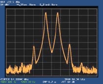
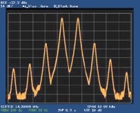
- EDSP contours (low-, mid- and high-cut) - EDSP Audio peaking filter (APF for CW and data) - EDSP noise reduction (NR) - DSP auto-notching (but outside the AGC loop) - IDBT (replace the bandpass DSP filter) In addition to these DSP capabilities, the FT-1000MP provides several manual filters : - IF notch filters - VRF passband filter - Bandwidth filters (NOR, NAR1, NAR2 filter selection for the three IF stages) - Noise Blanker (NB) - Microphone Equalization circuits In addition digital modulation and demodulation features are also included in order to improve the noise figure compared to traditional analog circuits. This being said, many short reviews wrote similar comments and state that the Mark-V is a winner without more explanation, but here is a first example of the excellent performances of the Mark-V filtering. Self-explanatory examples What are the performances of these DSP filtering when they are applied to HF signals ? Imagine that you desire to remove a tune incoming at the HF stage. Begin by switching on one analog filter and you will immediately hear the tune vanishing abruptly when it will tops over the filter's edge, leaving behind only a few hoarse key clicks. At the audio and without oscilloscope that already confirms the high Q of the Mark-V selectivity. The contour of Collins filters passband is indeed very effective at removing noises on sideband, without impacting the desired signal. This effect is caused by the short skirts of the analog filters which profile is similar to a square wave. Take another example, this time using the 2.4 kHz DSP filter. In presence of a powerful signal as strong as S9+60 dB on the 10m band (thus 50 V ! knowing that S9 is 50 mV, the dB expressing a power ratio), where the process must be still more severe, the drop into the "hash" of the background noise does not extend over 200 Hz where its competitors reach with difficulties 700 Hz. The skirts of this DSP filters are thus really very steep. In a third test, at 100 kHz from a so strong tune, the DSP continues to work, dropping the interferences just above the background noise without really increasing the hash. Other so-called high-end transceivers (e.g. ICOM) are so badly programmed that the hash is increased over 20 dB ! These three results using both the analog and digital filters are really remarkable in many conditions of traffic, confirming the narrow skirts and bandwidths of filters installed in the Mark-V. These characteristics, rarely seen on other high-end rigs impact greatly and positively the selectivity of its receiver. We will come back on these performances on the next page when we will speak about intermodulation and preamplifications means that display also excellent figures. AGC and bandwidth adjustment But there is however one small problem, mainly if you work in CW. In some conditions the 4th IF stage (DSP) of the Mark-V is badly adjusted to the filters. From factory the DSP bandwidth for CW reception is set to 2.0 kHz but the supplied CW filter is 2.4 kHz wide ! Do you see what I mean... This mismatch means that strong CW signals might be present on the DSP filter skirts and they will capture the AGC, preventing you to listen to weak signals. Explain
in a few words how work this AGC. A signal "captures" the AGC if
it causes AGC action in the receiver, which We can solve this problem in the Mark-V in either disabling the DSP or installing the optional 2.0 kHz CW filter at the 4st IF stage. EDSP features In my previous transceiver (Kenwood TS-570D) I was impressed by the efficiency of the SSB Noise Reduction filter (N.R1), a DSP feature that reduced the white noise of a lot of dB, allowing to hear QSO in much better conditions. In changing of rig I hoped to find back a similar tool and new ones. I was also far to be disappointed.
Located just at left of the main VFO tuning knob, the EDSP features is constituted of three sets of digital controls (using maths algorithms), each being associated to a selector located at the bottom of the layout. On the left part and a bit embossed, are the Audio peaking filters (APF) and Noise Reduction filters (NR). The APF is dedicated to weak CW signals or data, offering respectively 240, 120 and a very narrow 60 Hz bandwidth. They are associated to green lights. To its right are the four NR filters. They cut undesired noises, it is man-made (near QSO, tune, RFI, etc) or natural (QRN generated by atmospherics). In both cases you can select them each after another to find the most effective. The results at audition are obvious and you take pleasure to activate them to cutting back any kind of noise. On the right part of the layout are the three contours filters (there were four on the FT-1000, the 4th being replaced by the IDBT) each associated to a icon showing its profile. Each filter provides a preset digital audio emphasis. They are associated to a light that becomes green for the low-cut, orange for mid-cut and red for hig-cut. In the picture the mid-cut was activated as well as the NR "B" and APF with a bandwidth of 240 Hz. The EDSP works at the 11 kHz IF and audio stages of the transceiver. This explain why it improves so much the receiving and can so easily or almost reduce interferences. Even the DSP filters installed at the audio stage of my old Kenwood TS-570D, famous for its quality/price ratio and DSP options, can not fight against these Enhanced DSP features installed at the IF stage of the Mark-V. Where new transceivers use a fast 32-bit processor, the Mark-V EDSP still uses a 16-bit processor running at 33 MHz. It is far to be performing for the simple reason that it was in fact purely and simply extracted from the first model of the FT-1000MP released in 1996 and placed as it in the new "MP" without the slightest change. Even if this module works fine, over a decade after its creation it is somewhat outmoded, and this is not to reinforce the quality service of Yaesu. EDSP features are available for transmission as well, in providing a significant improvement of your signal quality up to reach a "broadcast audio" when used in combination with a customized carrier frequency (a Menu option). Like the EDSP, the microphone equalizer works also at the IF and audio stages of the transceiver to suit at best to your voice characteristics. Noise Blanker In practice before using the EDSP filters (thus upstream of the filtering), the Mark-V offers two Noise Blanker filters (NB) that work on the IF stage; they are thus much more efficient than any filter installed on the next stages (I think about the audio stage of course). Only drawback, the selection of one or another filter must be set using the Menu option 2-8 (nb), a procedure that is one more time not practice at all. The "A" filter (set on A1-A15) is suited to remove short pulse signals (e.g. RFI from nearby engines or power lines) while the "B" filter (set to B1-B15) removes statics and strong so-called "white noise". Personally I consider that the "B" setting is more useful because long and irregular pulses (QRM or QRN) are much more present on bands that short pulses (at least in my experience at home located in the country). If the RFI are very strong but short you can set the NB to the highest values (A15 or B15) and use the combination of knobs FAST + NB. The result is quite impressive although I find that the FAST generates undesirable pulsed noises. If in addition you enable the EDSP functions, there is no doubt that you will drastically reduce or even remove the interferences of any kind. A must. At last, although the auto-notching remains outside the AGC loop, its activation produces an immediate result in cutting any unsollicited tune or QRM centered on your frequency. As we seen previously, you can also select a manual IF notch filter via the Menu, option 2-9 (NotcH), to shape some filters on the fly or cascading the DSP and the IF notch filters if you need to improve a weak signal, so much features unavailable in mid-range transceivers. Enhanced EDSP Modulation/Demodulation Placed offline by default, the EDSP Modulator is an electronic circuit placed on the 4th IF stage able to improve the transmitter signal-to-noise ratio offering a very flat frequency response. In addition it offers a choice of four cutoff frequencies of 100, 150, 200, or 300 Hz on the low-frequency side and a high-frequency cutoff at 3100 Hz. Linked to the SSB bandwidth within the EDSP, you can select either 100-3100 Hz or 300-2800 Hz filters in the EDSP Demodulator circuit to get very low noise without the least distortion. This is a convenient way to smooth your audio when ragchewing in local QSO but also during long DX contacts. This circuit is also enable on AM and CW but only for receive purposes. Its parameters can be set via Menu option 7-7 (dSP-ndn). Next chapter Selectivity, sensitivity and IMD
|
|||||||||||||||||||||||||