|
|
|
Optical aberrations
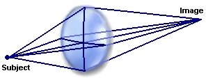
All you need to know about optical aberrations (I) Generally speaking, aberrations are errors occuring in the resulting image which is not conform to the subject. By design any optic using a lens or a mirror is sensible to optical aberrations. This phenomenon is caused by the nature of light and several parameters like the index of refraction, Abbe number, the density and coefficient of dilatation of the optical glasses which vary with the wavelength, the temperature, and the light beam position entering the objective or the eyepiece (incidence angle and off-axis position). An aberration is thus depending on parameters or constants and variables. At various intensity all these inputs may produce well-known aberrations as chromatic, coma, spherical, astigmatism, field curvature and geometrical distortions. How appear these aberrations, how to recognize, reduce or supress them ? We are going to answer to all these questions. From Snell's Law to Zernike polynomials At school, we all learnt that a ray of light passing through a lens is refracted. Snell's Law or law of refraction know as the Descartes's Law of sines, describes how rays of light change of direction at the surface between two media having different indices of refraction. We all know that when a ray moves from a low-index medium like the air to a high-index medium like a lens its bends toward the normal (perpendicular) to the plane; from high-index to low, it bends away from the normal.
Although Snell's Law is exact, if we consider higher orders of the sine expansion, we discover slight alterations to the predictions of first-order theory. To solve the equation the following non-zero term must be added : This term permits to define what we call the third-order, or Seidel aberrations. However this relation models a surface thanks to the development of series and is thus approximative. Therefore Fritz Zernike developed a new model based on polynomials that bear his name taking into account an infinite number of polynomial terms to describe all aberrations. Thanks to this Zernike polynomials we can compute and model a real surface from an ideal circular wave surface generated by a wavefront analyzer (or an interferometer) and decomposing it into a set of polynomials, each corresponding to a particular aberration. The resulat is dispayed in the form of tables of numbers, isophote areas or curves that measure the difference between the actual surface and that of an ideal sphere. Note, however that the result is projected on a flat surface and not spherical. In practice, nobody uses the full Zernike polynomials and one generally use ~25 terms to characterize the main aberrations until the 7th order. To read : Measurement report of Astro-Physics StarFire 155 mm f/7, Airy Lab Application of Zernike polynomials
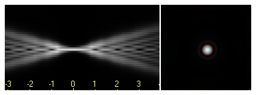
The core strength of this equation is to represent each aberration by one or more terms with a power (exponent) depending on the order. It is why we speak of aberrations of first, second, third order, etc. More the equation includes orders, the more accurate is the curve that to infinity totally matches with the real profile of the aberration. Moreover, since some surfaces are slightly skewed, the aberrations may vary depending on the position of the incident beam relative to the axis. To account for this, each term is associated with two coefficients corresponding to the 45° and 90° axis. If the surface is of revolution, we consider only one term (the case of the spherical aberration or focus). In addition to the measurement of each aberration of the outgoing wavefront, one can also measure the error on the transverse ray that defines the blur of a focused imagethat can also easily be geometrized. The first four terms of Zernike polynomials are not aberrations but characterize the surface positioning (piston or offset in height, the adjustment of misalignment or tilts and the focusing). Then come the third-order aberrations. Although numerous, they can be classified into two broad categories : monochromatic aberrations and polychromatic aberrations. If polychromatic aberrations relate to color, monochromatic aberrations or Seidel aberrations degrade (spherical aberration, coma and astigmatism) or distorted (curvature of field and distortion) the image generated by lenses or mirrors. Thus, the first 5 terms of the third order aberrations are the best known : the 4th and 5th terms define astigmatism, the 6th and 7th terms coma and the 8th term is the spherical aberration. At last, the 9th and 10th terms describe the 5th-order aberrations such as trefoil. Superior orders merely repeat previous aberrations by adding more specific developments. In this article we will review the various aberrations up to the 3d order. The cross-section of a light bending can be plotted, showing rim ray curves. We can also display the ray distribution using a scatter plot or spot diagram. From the shapes and sizes of these patterns a trained experimenter can deduce which forms of aberrations are present and their intensity. So with this information and the characteristics of glasses used he can plan to correct these aberrations. This science requires however to translate these aberrations in terms of polynomials and to find a way to assign them to specific surfaces in the lens or to other parameters like the density of glass.
In a single positive lens made of ordinary glass, such as Crown glass, an enlargement of the theoretical focal plan displays a fuzzy and colored blop as each wavelength of light focus at a different position like does a prism. In the field looking through such a scope the image of bright objects look like blurry and has a fringe of false colors. Technically speaking, this scope is subject to chromatic aberration and displays what we call a secundary spectrum. Hopefully reflectors don't suffer from this effect as they use a mirror to transmit the light to the eyepiece, but this latter does. If this phenomenon is exploited to separate light through a prism, observers rarely need a spectroscop, but rather a scope able to display images without aberrations... A second aberration called spherical aberration, occurs when surfaces of glasses or mirrors are not properly figured or shaped. As with chromatic aberration, the focal plane becomes blurry and that effect depends how far you are from the center. Coma aberration is a variante of this effect. Other aberrations like astigmatism occurs when an incident ray strike the lens asymmetrically. At last field curvature and distortions are related to the shape of the surface of the glass. Master opticians can reduce and even suppress all these aberrations from a few minuts to a few degrees off-axis. The first attempts were to make telescopes longer to increase the f/ratio in order the intensity of aberrations becomes less pronounced. This explains why scopes using a short focal ratio, often called "fast telescopes" by reference to photography, are more subject to chromatic aberration than some others "slower". But if making telescopes longer is without inconvenient for small scopes, which stay light and rigid, that becomes a really challenge for the widest ones, which resulting focal extends over 10 meters or even tens of meters if the lens reaches 1 m of aperture like the famous Yerkes or Paris-Meudon refractors.
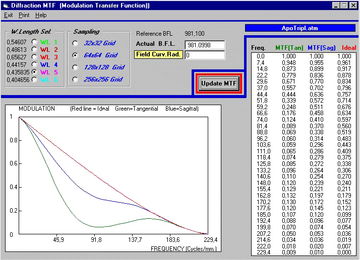
So designers have approached the problem in another way by searching for glasses - among 2000 available - having a different index of refraction to rectify the chromatic aberration. For example, using a positive, low-index, BK7 Crown glass in conjunction with a negative, high-index, F2 Flint glass, designers are able to "bend" all wavelengths nearly at the same point. When two colors cross the focal plan the resulting scope is called an achromatic refractor. When the objective is able to cross most of the visual spectrum at the focal point, including infrared (useful for CCD applications), and sometimes violet end (near UV), and complementary to correct the other aberrations, the resulting scope is refered as an apochromat. In the past, few manufacturers sold apochromats using 2 lenses, today most of them and mainly Japanese's provide such models using Fluorite elements (ED) but they are very expensive compared to achromatic refractors. For more detail about this topic read my page dealing with coatings and dispersion as well as the archives of Yahoo! Refractors egroup. Evaluation and simulation There is another way than the test in laboratory to evaluate an optical system. Today, master optical designers make usage of optical design software. These programs permit to simulate the behaviour of a lens before it is built and to predict the resulting image quality. These tools output to various imaging systems to display all images characteristics, among which spot diagrams, encircled energy (PSF), and MTF are the most common.
It is obviously more easy to use software to create lenses than trying to correct aberrations by assembling physically lenses. Worse, when you try to correct aberrations in one place it often pops up in another, making the optimization of these designs a real challenge. So in short, all aberrations are mainly inherent to the design of a telescope. Within the same design and never with others, it is reasonable to assign a value of the aberrations depending of F-number. Different designs have different properties. Generally however, the more steply the curved lenses or mirrors, the more optical aberrations there will be. Some 200 years ago this lead observers to use f/500 telescope in order to reduce the chromatic aberration. Some other aberrations like coma were insignifiant in those telescopes, so was their field of view ! Fortunately, optical engineers helped us to solve these problems.
Next chapter Chromatic, spherical and coma aberrations |
||||||||||||||||||||||||||||||||