


Meade® 7" LX200 Maksutov-Cassegrain Telescope
8", 10", and 12" LX200 Schmidt-Cassegrain Telescopes
A. INTRODUCING THE MEADE LX200
As a new LX200 owner, you are preparing for a journey into the universe with the most advanced amateur telescope ever produced. The advent of this instrument is the culmination of twenty years of innovation and design at Meade Instruments; never before have the features you have in your hands been available to amateur astronomers: from robotic object location to the revolutionary Smart Drive and the most stable mounting structure ever. Your telescope comes to you ready for adventure; it will be your tour guide and traveling companion in a universe of planets, galaxies, and stars.
Meade 8", 10", and 12" LX200 Schmidt-Cassegrain and 7" Maksutov-Cassegrain telescopes are instruments of advanced mirror-lens design for astronomical and terrestrial applications. Optically and mechanically, the 7", 8", 10", and 12" telescope models are perhaps the most sophisticated and precisely manufactured telescopes ever made available to the serious amateur. These telescopes enable the visual astronomer to reach out for detailed observations of the Solar System (the planets: Jupiter, Saturn, Mars) and beyond to distant nebulae, star clusters, and galaxies. The astrophotographer will find a virtually limitless range of possibilities since, with the precision Meade worm-gear motor drive system, long exposure guided photography becomes not a distant goal, but an achievable reality. The capabilities of the instrument are essentially limited not by the telescope, but by the acquired skills of the observer and photographer.
The 7", 8", 10", and 12" LX200 are, with the exception of a few assembly operations and features, almost identical operationally. Most standard and optional accessories are interchangeable between the three telescopes. The instructions in this manual generally apply to all three telescopes; when exceptions to this rule occur, they are clearly pointed out.
If you are anxious to use your Meade LX200 Telescope for the first time, at the very least be sure to read Telescope Assembly and Quick Start sections of this manual. Thereafter, we urge you to read the balance of this manual thoroughly at your leisure, in order that you may fully enjoy the many features offered by the instrument.
1. What Is the LX200? An Overview
Meade LX200 SCT's mark a new era in telescope technology for the amateur astronomer, whether beginner or seasoned veteran. For the beginner LX200 electronics permit the location and observation of the major planets as well as hundreds of deep-sky objects the very first night you use the telescope. For the experienced amateur the telescopes' pushbutton electric slewing, digital readouts, Smart Drive, and much more open up visual and photographic capabilities heretofore undreamed of.
a. Heavy-Duty Mounts with 9-speed Dual-Axis Electronics
DC-servo-motor-controlled worm gear drives on both telescope axes permit observatory-level precision in tracking, guiding, and slewing. The 9-speed dual-axis drives cover every possible contingency of telescope positioning: Press the SLEW button on the keypad controller for rapid motion of the telescope across the skies at up to 8 degrees per sec. (6 degrees per sec. for the 12" LX200) on both axes simultaneously; once near the target, switch instantly to the FIND speed for centering in the viewfinder at 2 degrees per sec. Observing the object in the main telescope, use the CNTR speed (32x sidereal) to place the object in the center of the field. During long-exposure astrophotography press the GUIDE button for precise corrections at 2x sidereal speed.
b. Built-in 64,359-Object Library
Enter into the keypad any of the 110 Messier objects, 7,840 of the finest NGC objects (galaxies, diffuse or planetary nebulae, star clusters), one of the 8 major planets from Mercury to Pluto, one of 351 alignment stars or any one of 56,050 SAO, UGC, IC or GCVS objects, press GO TO, and the telescope automatically slews, or moves, to the object at up to 8° per sec., centering it in the main telescope field.
c. Altazimuth Mode Operation
For all visual observing applications, and for lunar and planetary photography, Meade LX200's may be set up in the Altazimuth mode. Just attach the telescope's drive base directly to the tripod, use the fast 1-star alignment procedure, and the telescope's computer actuates 2-axis tracking that keeps objects precisely centered in the field, even at high powers, during the entire observing session.
d. Terrestrial Operation
Meade LX200's make incredible land-view telescopes. Set the telescope up in the Altazimuth format, activate the Land menu option on the telescope's computer, and use the Keypad to track land objects on both axes at any of the same 4 drive speeds!
e. Keypad and Power Panel Functions
The multifunction capability of LX200's includes direct connection of popular CCD autoguider/imagers; RS- 232 serial interface with a personal computer (PC), allowing the user to perform all of the Keypad functions through, or write custom telescope software for a PC; brightness level control of an illuminated reticle eyepiece from the Keypad and including special pulse-mode reticle operation.
2. Standard Equipment
a. 7" Model LX200
lncludes 7" Maksutov-Cassegrain optical tube assembly with EMC super multi-coatings (D = 178mm, F = 2670mm-f/15); heavy-duty fork mount, with 4"-dia. sealed polar ball bearing, quartz-microprocessor-controlled 5.75" worm gears on both axes; setting circles in RA and Dec; handheld keypad Electronic Command Center with digital readout display, permanently-programmable Smart Drive, 9-speed drive control on both axes, GO TO controller, High-Precision Pointing, and 64,340-object onboard celestial software library; internal tube-cooling fan for rapid image stabilization; 25 ft. power cord and adapter for telescope operation from 115v.AC; 8 x 50mm viewfinder; eyepiece-holder and diagonal prism (1.25"); Series 4000 SP26mm eyepiece; variable-height field tripod; operating instructions.
b. 8" Model LX200
lncludes 8" Schmidt-Cassegrain optical tube assembly with EMC super multi-coatings (D = 203mm, F = 1280mm-f/6.3 or 2000mm-f/10); heavy-duty fork mount, with 4"-dia. sealed polar ball bearing, quartz-microprocessor-controlled 5.75" worm gears on both axes, and multi-function power panel display on the drive base; manual and electric slow-motion controls on both axes; setting circles in RA and Dec; handheld keypad Electronic Command Center with digital readout display, PPEC Smart Drive, 9-speed drive control on both axes, GO TO controller, High-Precision Pointing, and 64,340-object onboard celestial software library; 25 ft. power cord and adapter for telescope operation from 115v.AC; 8 x 50mm viewfinder; eyepiece-holder and diagonal prism (1.25"); Series 4000 SP26mm eyepiece; variable-height field tripod; operating instructions.
c. 10" Model LX200
lncludes 10" Schmidt-Cassegrain optical tube assembly with EMC super multi-coatings (D = 254mm, F = 1600mm-f/6.3 or 2500mm-f/10); heavy-duty fork mount, with 4"-dia. sealed polar ball bearing, quartz-microprocessor-controlled 5.75" worm gears on both axes, and multi-function power panel display on the drive base; manual and electric slow-motion controls on both axes; setting circles in RA and Dec; handheld keypad Electronic Command Center with digital readout display, PPEC Smart Drive, 9-speed drive control on both axes, GO TO controller, High-Precision Pointing, and 64,340-object onboard celestial software library; 25 ft. power cord and adapter for telescope operation from 115v.AC; 8 x 50mm viewfinder; eyepiece-holder and diagonal prism (1.25"); Series 4000 SP26mm eyepiece; variable-height field tripod; operating instructions.
d. 12" Model LX200
lncludes 12" Schmidt-Cassegrain optical tube assembly with EMC super multi-coatings (D = 305mm, F = 3048mm-f/10); heavy-duty fork mount, with 4"-dia. sealed polar ball bearing, quartz-microprocessor-controlled 5.75" worm gears on both axes, and multi-function power panel display on the drive base; manual and electric slow-motion controls on both axes; setting circles in RA and Dec; handheld keypad Electronic Command Center with digital readout display, PPEC Smart Drive, 7-speed drive control on both axes, GO TO controller, High-Precision Pointing, and 64,340-object onboard celestial software library; 25 ft. power cord and adapter for telescope operation from 115v.AC; 8 x 50mm viewfinder; 2" diagonal mirror with 1.25" adapter; Series 4000 SP26mm eyepiece; giant field tripod; foam-fitted carrying case; operating instructions.
B. UNPACKING AND INSPECTION
As you begin to unpack your telescope from its cartons, you will probably be interested in setting it up right away; we certainly understand your excitement but please take a few minutes to read this page before doing so. You should verify that you have all the proper equipment, and that it has arrived to you undamaged.
We strongly recommend that you keep your original packing materials. If it should ever become necessary for you to return your telescope to the Meade factory for servicing, these will help ensure that no shipping damage will occur.
Meade LX200 telescopes supplied to countries outside the U.S.A. are identical to those offered domestically, with the exception of the AC wall adapter.
1. What You Should Have
Carefully unpack and remove all the telescope parts from their packing material. Compare each part to the Standard Equipment list on page 9. You may wish to place a check next to each item as you identify it. These Packing Programs represent the original specifications for this instrument. Each telescope has been inspected twice at the factory to confirm the inclusion of every item.
2. Please Look Everything Over
Meade Instruments and your shipper have taken precautions to ensure that no shipping damage will occur, but if your shipment has suffered severe vibration or impact damage (whether or not the shipping cartons show damage) then it is important that you retain all the original packing and contact the shipper to arrange a formal inspection of the package or packages. This procedure is required prior to any warranty servicing by Meade Instruments.
3. Inspecting the Optics: Note on the "Flashlight" Test
If a flashlight or other high-intensity light source is pointed down the main telescope tube, you may at first be shocked at the appearance of the optics. To the uninitiated, the view (depending on your line of sight and the angle the light is coming from) may reveal what would appear to be scratches, dark or bright spots, or just generally uneven coatings, giving the appearance of poor surface quality. These effects are only seen when a high intensity light is transmitted through lenses or reflected off the mirrors, and can be seen on any high quality optical system, including the giant research telescopes in use today. It should be pointed out, however, that optical quality cannot be judged by this grossly misleading "test", but through careful star testing. The Flashlight Test causes even the very best optics to look "terrible."
As the high intensity light passes through the Schmidt corrector plate, most of it is transmitted through (about 98%+) while the rest of the light scatters through the glass. As the light hits the mirrored surfaces, most of it is reflected back (about 94%) while the rest of it scatters across the coatings. The total amount of scattered light will be significant, and its effects allow you to see microscopic details that are normally invisible to the unaided eye. These anomalous details are real, but their combined effects will in no way impose limits on the optical performance, even under the most demanding observing or imaging criteria.
4. Caution: All LX200 Owners
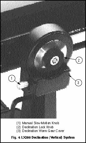
Serious damage to the drive gears may result from shock in handling, while transporting or commercially shipping the LX200, should the R.A. Lock (7, Fig. 3), and/or the Dec. Lock (2, Fig. 4) be left engaged. Always release the locks when storing in the case, or when crating for commercial shipment to allow the telescope to give, if the case or crate is sharply jarred or dropped.
Also, the optical and mechanical axes of all LX200 telescopes have been carefully aligned at the factory to ensure accurate object pointing. Do not loosen or remove the fork arms or optical tube assembly from the drive base; the resulting misalignment of the axes will result in inaccurate slewing of the telescope in the GOTO mode.
5. Caution: 10" and 12" LX200 Owners
Do not attempt to turn the focuser knob of the optical tube until you have read this note!
Next to the base of the focuser you will see a red-colored slotted head bolt. This bolt is used only for safety in shipment. Remove this bolt before attempting to turn the focuser knob. In its place, insert the rubber plug provided as a dust protector (this rubber plug is included with your hardware package).
Your focuser is now operational.
Warning! The 10" and 12" LX200 should never be commercially shipped without this red-colored bolt in place. This is essential during commercial transport where rough handling may occur. For your personal transport and storage, you will never have to use this bolt again.
a. TO COMMERCIALLY RE-SHIP THE 10" OR 12" LX200, BE SURE TO FOLLOW THIS PROCEDURE:
1. Turn the focuser knob clockwise until it stops. This will bring the primary mirror all the way back in the tube.
2. Remove the rubber plug and insert the red-headed bolt. Thread it in to a firm snug feel. Do not overtighten. (If you have misplaced the red-headed bolt, you may use any other bolt that is 1/4-20x1" long.
3. When packaging the 10" or 12" LX200, be sure to release the R.A. Lock (7, Fig. 3), and Dec. Lock (2, Fig. 3), to prevent shock to the gears in the motor assemblies should the package suffer severe handling.
Please note that commercial shipment of the 10" and 12" LX200 Telescope without the safety bolt in place and packed in the original factory supplied shipping containers as described above is done at the owner's risk and your warranty may be voided if shipping damage results.
6. Keypad Version Number
The current keypad version is 3.20 (see sticker on back of keypad). This does not indicate the telescope software versionwhich is displayed on the keypad LED at power-up.
C. TELESCOPE ASSEMBLY
Use the following steps to assemble your telescope. Note: Section headings list which LX200 model (7", 8", 10" or 12") is covered under that heading.


1. The Field Tripod (7", 8", 10" and 12" LX200 Models)
The Field Tripods (Figs. 1 and 2) for Meade 8", 10", and 12" LX200 telescopes are supplied as completely assembled units, except for the spreader bar (4, Fig. 1) and the 6 lock knobs (2 knobs for each of the 3 tripod legs) used to adjust the height of the tripod. These knobs are packed separately for safety in shipment.
For visual (i.e. non-photographic) observations, the drive base (17, Fig. 3) of the telescope's fork mount is attached directly to the field tripod. The telescope in this way is mounted in an "Altazimuth" ("Altitude-Azimuth," or "vertical-horizontal") format. The telescope in this configuration moves along vertical and horizontal axes, corresponding respectively to the Declination and Right Ascension axes (explained later in this manual) in an astronomical observing mode.
Alternately, the field tripod can be used in conjunction with the appropriate optional equatorial wedge (see Appendix A for instructions of the use of the equatorial wedge) for long exposure astrophotography. The equatorial wedge permits alignment of the telescope's Polar Axis with the Celestial Pole (or North Star).

After removing the field tripod from its shipping carton, stand the tripod vertically, with the tripod feet down and with the tripod still fully collapsed (see Fig. 2). Grasp two of the tripod legs and, with the full weight of the tripod on the third leg, gently pull the legs apart to a fully open position.
Thread in the 6 lock-knobs (2 on each tripod leg) near the foot of each tripod leg. Refer to Fig. 1. These lock-knobs are used to fix the height of the inner, extendible tripod leg sections. Note: "Firm feel" tightening is sufficient; over-tightening may result in stripping of the knob threads or damage to the tripod legs and results in no additional strength.
The spreader bar (4, Fig. 1) has been removed for shipment. To replace, first remove the threaded rod (2, Fig. 1) from the tripod head (1, Fig. 1); a small piece of plastic holds the threaded rod in place. Remove the small plastic bag that is stapled to the threaded rod. This bag contains the "C" clip retainer (used below) and an extra clip.
Slide the spreader bar onto the threaded rod (note the correct orientation as shown in Fig. 1) and position the threaded rod back through the tripod head. Place the clip retainer ( a "C" clip) into the slot in the threaded rod. This clip holds the threaded rod in place. See Fig. 2.
Position the spreader bar so that the 3 arms of the spreader bar are lined up with the 3 tripod legs.
Place the entire telescope (as shown in Fig. 3) onto the top of the tripod head, and thread the threaded rod into the central threaded hole in the bottom of the drive base of the telescope. Tighten the tension knob (3, Fig. 1); firm tightening of the tension knob is sufficient to result in rigid positioning of the tripod legs.
To vary the tripod height, loosen the 6 lock-knobs, slide the 3 inner tripod leg sections out to the desired height, and firmly re-tighten (but do not overtighten) the 6 lock-knobs.
To collapse the tripod (after removing the telescope and equatorial wedge, if applicable) for storage follow these steps:
1. Rotate the spreader bar 60° from its assembled position, so that one spreader bar arm is located between each adjacent pair of tripod legs.
2. At the base of the tripod is a 3-vane extension strut system, with a circular hub at its center (7, Fig. 1). Grasp the tripod head (1, Fig. 1) with one hand and, with the other hand, pull directly "up" on the central hub of the extension strut system. This operation will cause the tripod legs to move inward to a collapsed position.
1. If the tripod does not seem to extend or collapse easily, do not force the tripod legs in or out. By following the instructions above, the tripod will function properly, but if you are unclear on the proper procedure, forcing the tripod into an incorrect position may damage the extension strut system.
2. Do not overtighten the 6 lock-knobs used to fix the inner tripod leg sections at various heights. "Firm feel" tightening is sufficient.
3. Be sure the spreader bar (4, Fig. 1) is not upside-down on the threaded rod.
2. Mounting the Viewfinder (7", 8", 10", and 12" LX200 Models)
Each 7", 8", 10", and 12" LX200 telescope is supplied as standard equipment with an 8x50mm straight-through viewfinder. The bracket for this viewfinder is packed separately from the finder itself, and 6 black nylon thumbscrews for collimation are pre-threaded into the viewfinder bracket. The viewfinder bracket mounts onto the telescope with a quick-release mount. See Fig. 3.
a. Attaching the Viewfinder
The viewfinder is shipped separately from the bracket and must be installed into the bracket. Slide the viewfinder into the bracket and lightly tighten the 6 collimation (alignment) screws (2, Fig. 3).
The quick-release mount allows the viewfinder to be easily attached or removed from the telescope. To attach the unit, simply slide the viewfinder with bracket into the mating base on the telescope and tighten the two thumbscrews.
b. Focusing the Viewfinder
The viewfinder has been pre-focused at the factory. However, should it become necessary to adjust the focus, follow these steps:
1. Loosen the Focus Lock Ring (18, Fig. 3).
2. While looking at a star, rotate the Dew Shield (1, Fig. 3) until the star is in focus. (This refocuses the objective lens.) CAUTION! Take care when rotating counter clockwise. You are unthreading the dew shield and it may fall off if rotated too far. Refocusing the objective lens will only require a few turns of the Dew Shield at most.
3. When the Dew Shield is rotated to the sharpest focus for your eye, tighten the Focus Lock Ring against the Dew Shield to fix its position.
c. Collimating the Viewfinder
The viewfinder will require alignment, or collimation, with the main telescope. Using the 26mm eyepiece, point the main telescope at some easy to find land object (e.g. the top of a telephone pole or corner of a building) at least 200 yards distant. Center a well-defined object in the main telescope. Then, simply turn the 6 nylon collimation thumbscrews (2, Fig. 3) until the crosshairs of the viewfinder are precisely centered on the object already centered in the main telescope. With this collimation accomplished, objects located first in the wide-field viewfinder will then be centered in the main telescope's field of view.
3. Attaching the Diagonal Prism and Eyepiece
The eyepiece holder (6, Fig. 3) threads directly onto the rear-cell thread of the 8" and 10" telescopes. The diagonal prism (13, Fig. 3) slides into the eyepiece holder of the 7", 8" and 10" telescopes, while the 2" diagonal mirror threads directly into the rear-cell thread of the 12" telescope. In turn, both the diagonal prism and diagonal mirror accept the supplied 1 1/4" O.D. eyepiece.
For astronomical observations, the diagonal prism or mirror generally provides a more comfortable right-angle viewing position. Alternately, in the 8" and 10" telescopes, an eyepiece may be inserted directly into the eyepiece holder for straight-through observations, the 12" telescope requires the accessory eyepiece holder. Note in this case, however, that the image will appear inverted and reversed left-for-right. With the diagonal prism and mirror, telescopic images appear correctly oriented up-and-down, but still reversed left-for-right. For terrestrial applications, where a fully corrected image orientation is desired, both up-and-down and left-for-right, the optional #924 Erecting Prism* or #928 45° Erect-Image Diagonal Prism* should be ordered separately. Eyepieces and the diagonal prism are held in their respective places on the telescope by a moderate tightening of the thumbscrews on the diagonal prism and eyepiece holder.
4. Checking the Collimation of the Optics
The optical systems of all Meade Schmidt-Cassegrains are precisely collimated, or aligned, before leaving the factory. However, if the telescope has received a severe jolt in shipment the optics can become de-collimated, a situation which may result in serious image degradation. Recollimating the optics is, however, a simple procedure which is easily performed by the telescope user. We urge all LX200 owners to confirm the collimation of their telescope, and to recollimate the optics if necessary.
There is no collimation procedure required for the Meade 7" Maksutov-Cassegrain telescope. Factory alignment assures optimal viewing accuracies.
5. 12" Tube Swing-Through Limit
The length of the 12" LX200 optical tube prohibits the correcting plate end of the tube from swinging through the fork armsthe tube will hit the mount. When the telescope is aligned, the software will stop the telescope from moving into the mount. If the telescope is not aligned, there are also mechanical stops.
When in LAND or ALTAZ modes, this limit does not restrict any sections of the sky, since the limit is set at 45° from straight down. But when in the POLAR mode, some parts of the sky might be restricted, depending on the latitude of the observing site.
Observing sites with latitudes higher than 45° will not have any restrictions. Latitudes below 45° will have the southern horizon restricted somewhat. To determine the amount of sky not available, subtract the latitude of the observing site from 45. This will give the number of degrees of southern horizon that the 12" LX200 will not move to. For example, if the latitude of the observing site is 35°, then 10° (45-35) of southern sky is unavailable for observations.
6. 7" Tube Swing-Through Limit
The length of the 7" LX200 optical tube prohibits the correcting plate end of the tube from swinging through the fork arms--the tube will hit the mount. When the telescope is aligned, the software will stop the telescope from moving into the mount. If the telescope is not aligned, there are also mechanical stops and some parts of the sky might be restricted if using a wedge, depending on the latitude of the observing site.
Observing sites with latitudes higher than 45° will not have any restrictions. Latitudes below 45° will have the southern horizon somewhat restricted when using a wedge and polar aligning. To determine the amount of sky not available, subtract the latitude of the observing site from 45, this will give the number of degrees of the southern horizon that the 7" LX50 will not reach. For example, if the latitude of the observing site is 35°, then 10° (45 35) of southern sky is unavailable for observations. No restrictions of observable sky occur in the altaz mode of alignment and operation.
7. Maksutov Fan
The Maksutov optics are equipped with a fan which will assist in the stabilization of the temperature of these optics. The fan will operate when a special power cord (supplied in the accessory box) is plugged into the fan and the LX50 panel plug marked "Aux" with the power switch in the "on" position. The amount of time required to stabilize the temperature will be dependent upon ambient conditions including the observation site and preexisting condition of the telescope. The fan should be activated at the beginning of the observation session to accelerate the temperature stabilization. As soon as the optics have reached an equilibrium with the environment the fan should be turned off by unplugging the fan power cord. Fan operation time should range between 5 and 25 minutes. While it is permissible to run the fan continuously it is not recommended because the very slight vibration of the fan may cause noticeable movement of the objects observed in the sensitive optics.
D. QUICK START
To utilize all the features of the telescope, it is necessary to enter some information into the telescope's computer memory, and learn the menu structure of the Keypad hand controller, which is described in the rest of this manual. As advanced as LX200 electronics are, the telescope is very straightforward to operateeven if you have no experience whatsoever in using a personal computer.
If you are reading this manual for the first time and are anxious to "look through the telescope", this section will describe how to use the telescope without going through the rest of the manual. But be sure to come back and read the details, for most of the telescope's features can not be accessed without a full knowledge of these details.
1. Using the LX200 Manually
The easiest way to use the telescope is to simply operate it manually. With the telescope mounted on the Field Tripod, and with the diagonal prism and eyepiece in place, you are ready to make observations through the telescope. Even without the viewfinder (if not yet installed), terrestrial objects will be fairly easy to locate and center in the telescope's field of view with a low power eyepiece, simply by "gun sighting" along the side of the main telescope tube.
By unlocking the R.A. Lock (7, Fig. 3), the telescope may be turned rapidly through wide angles in Right Ascension (R.A.). The reason for the terminology "Right Ascension" and its complementary term, "Declination" will be made clear further on in this manual. For now, "Right Ascension" simply means "horizontal" and "Declination" means "vertical". Fine adjustments in R.A. are made by turning the R.A. Slow-Motion Control Knob (8, Fig. 3), while the R.A. lock is in the "unlocked" position.
DO NOT ATTEMPT TO MOVE THE TELESCOPE MANUALLY IN A HORIZONTAL DIRECTION WHEN THE R.A. LOCK IS IN THE "LOCKED" POSITION.
The R.A. Slow-Motion Control Knob may be turned, if desired, with the R.A. Lock in a "partially locked" position. In this way, a comfortable "drag" in R.A. is created. But do not attempt to operate the R.A. Slow-Motion Control Knob with the telescope fully locked in R.A., as such operation may result in damage to the internal gear system.
Releasing the Declination Lock Knob (2, Fig. 4), permits sweeping the telescope rapidly through wide angles in Declination.
To use the Declination fine-adjust, or Manual Slow-Motion Knob, lock the telescope in Declination using the Declination Lock Knob (2, Fig. 4), and turn the Declination Slow-Motion Knob (1, Fig. 4).
With the above mechanical operations in mind, select an easy to find terrestrial object as your first telescope subject -- for example, a house or building perhaps one-half mile distant.
Unlock the Declination Lock Knob (2, Fig. 4), and R.A. Lock (7, Fig. 3), center the object in the telescopic field of view and then re-lock the Dec. and R.A. locks. Precise image centering is accomplished by using the Dec. and R.A. slow motion controls.
The Focus Knob (5, Fig. 3) is located at the "4 o'clock" position as you face the rear cell of the telescope. Focusing is accomplished internally by a precise motion of the telescope primary mirror so that, as you turn the focus knob, there are no externally moving parts. You will find that if you turn the focus knob counter-clockwise you are focusing towards the infinity setting, and turning clockwise is for close distance. There are about 45 complete turns to go from one end of focus to the other, and it is possible to focus past infinity. Be patient during focusing as images quickly go in and out of focus with only a slight amount of turning of the focus knob.
Before using the telescope manually during the daytime, be sure to read "Daytime Slewing."
2. Using the LX200 In Land
The 7", 8", 10", and 12" LX200 telescopes are shipped with the microprocessor set to Land, the align menu option you will wish to use to view terrestrial objects. In this menu option 4 different motion speeds are active, allowing the telescope to be moved electronically by means of the Keypad. To use the telescope in Land, follow these steps.
1. Loosen the Dec. Lock Knob (2, Fig. 4) and position the optical tube assembly approximately level, so that the Dec. Circle (3, Fig. 3) reads 0°. Retighten the Dec. Lock Knob.
2. Loosen the R.A. Lock (7, Fig. 3) and rotate the telescope so that the R.A. Pointer (9, Fig. 3) and the Hour Angle (HA) Pointer (16, Fig. 3) are approximately in line with each other. This will position the fork arms so that they are parallel to the Power Panel (11, Fig. 3). Tighten the R.A. lock
The above two steps are not necessary for the telescope to work, so don't worry about having to get it exactly right. The telescope has some "illegal" positions, places where the telescope will not go and these two steps insure proper operation.
3. After setting up the telescope, plug in both coil cords with the Keypad, one of the supplied power sources, either the AC Wall Adapter Power Converter (for AC current wall outlets), or the optional DC Cigarette Lighter Power Cord (used in an automobile's cigarette lighter outlet, with the ignition turned on only to allow the electric power on from the car battery).
 Motion Speeds
 GUIDE = 30 arcsec/sec, CNTR = 480 arcsec/sec, FIND = 2°/sec, SLEW = 8°/sec (8", 10"), = 6°/sec (12")
4. Turn on the power switch on the Power Panel of the LX200. The Keypad Display (1, Fig. 5) will show "MEADE" for several seconds as the microprocessor does a self-diagnostic test. When the self-diagnostic test is complete, the display will show "TELESCOPE" on the top line, "OBJECT LIBRARY" on the lower line, and the red LED light next to the "SLEW" button will light up.
5. At this point, the LX200 is ready to use. Select the speed at which you want to move the telescope by pressing the appropriate Speed Selection Key (4, Fig. 5). Note that you will be able to "see" the telescope move only in the SLEW and FIND modes; CNTR (center) and GUIDE motions can only be seen while looking through the telescope. The red LED next to that key (3, Fig. 5) will light, indicating the speed selected. Then press one of the four direction keys (2, Fig. 5) to move the telescope in that direction at the selected speed.
The LX200 can also be moved manually with the R.A. and Dec. locks released, or as described above only. The Declination Manual Slow-Motion Knob (1, Fig.4) is non-functional when power is supplied to the telescope. When the power is "on", only use the N, S, E, and W keys on the Keypad Hand Controller. Serious damage can occur to the internal gears of the motor assembly if the Declination Manual Slow-Motion Knob is turned even a slight amount by hand.
Before using the telescope during the daytime, be sure to read "Daytime Slewing."
3. Using the LX200 In Altazimuth (ALTAZ)
The two quick start methods described above allow you to use the telescope, but do not make use of any of the computer features available, including finding objects from the Object Library and automatic tracking of stars. In order for these features to work, the telescope's power needs to be "on", and the computer needs some basic information, which is entered through the Keypad. Once entered, the information is permanently remembered by the telescope's computer and need never be entered again, even if the telescope is turned "on" and "off" many times.
This section will explain what keys to push to get the minimum data required into the computer, without any detailed explanation. Later, see Section G, LX200 Modes for detailed instructions. These steps will only take a few minutes and will allow you to begin making use of all the LX200 features. Note also, much of this information can be skipped if using the UNKNOWN site.
a. Entering Basic Information
In order for the LX200 to make the conversions between the stellar coordinate system (R.A. and Declination) and the Altazimuth coordinate system (Altitude and Azimuth), it needs to know three pieces of information. This information only needs to be entered one time--the LX200 remembers the data even when the power is off.

1) Latitude and Longitude of the Observing Site.
NOTE: The SITE information cannot be entered if the telescope is in LAND mode. If the telescope is in LAND mode, the SITE menu option (Display 2, below) will appear in lower case letters. Follow steps 4-8 to change the telescope's operation to Altazimuth (ALTAZ) mode before proceeding.
You should find the position of your observing site to within 1 or 2 minutes of arc in both latitude and longitude. Many automobile, pilot, and topographical maps, as well as most atlases show latitude and longitude in 15 minute increments or better. The accuracy of the LX200 will depend on how close you get, so take a little time to get as accurate as you can.
Once the above information is determined, it can be entered into the telescope. It is easiest to enter the data with the telescope sitting on a table indoorsdo not try to do it outside at night.
Each step below is given without any details or explanations to keep the process as simple and fast as possible. Next to each step will also be a sample of what the Keypad Hand Controller display (1, Fig. 5) should look like after each step.
As an example, we will enter the data for Costa Mesa, CA (LAT=33°35', LONG=117°42'). If at any time you get "lost," simply turn off the telescope and restart this procedure.
1. Turn the telescope on. After a few seconds (after the self-diagnostic test is complete), the display will look like Display 1.
2. Press the ENTER key. This selects the TELESCOPE functions. The display should look like Display 2.
3. Press the ENTER key. This selects the SITE functions. The display should look like Display 3.
4. Press and Hold the ENTER key until the Keypad Hand Controller beeps. This selects the first site for editing. The display should look like Display 4, with the first "A" flashing.
5. Press the ENTER key. The display should look like Display 5.
6. Use the number keys to enter your Latitude. The underline designates the current cursor position. Mistakes can be corrected by moving back (using the "E" and "W" keys). A negative latitude can be entered by positioning the cursor under the "+" and hitting the "NEXT" key (lower right-hand key). When the Latitude is correct, press ENTER. The display will look like Display 6.
7. Use the number keys to enter your Longitude as above. When complete, the display will look like Display 7.
8. Press ENTER to complete the site information input. The display will go back to Display 3.
9. Press MODE to go back to Display 2.
10. Press MODE again to go back to Display 1.
It is important to note that the longitude standard used in the LX200 starts at 0 degrees in Greenwich U.K. and increases Westerly only to 359 degrees 59 minutes. Many maps will show Easterly longitudes which cannot be entered into the Keypad Display. As an example, if your map indicates that you are at an Easterly longitude of 18 degrees 27 minutes, then you would enter 341 degrees 33 minutes.
Do not concern yourself with differences in longitude and latitude as they pertain to different map spheroid projections, those minor differences are too small to adversely affect the longitude and latitude data input.
2) Local Time and Date.
The local time should be set as accurately as possible, using the 24 hour format. The local time and date are used to determine sidereal time (star time) and the pointing accuracy of the telescope will depend on the accuracy of the time entered. Choose a reliable source as a reference for accurate time such as your local airport, or telephone company. In the U.S.A. you can double check the accuracy of the exact minutes by dialing WWV for the universal coordinated time at (303) 499-7111 (be sure to enter your local time hour information, not the U.T. hour). For the example, we will use 4:25:00 P.M. on Jan. 15, 1992.
1. The display should look like Display 1. If it does not, press the MODE key until it does.
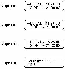
2. Press the MODE key twice. The display will look like Display 8, but with a random LOCAL and SIDE times.
3. Press and HOLD the ENTER key until the Keypad Hand Controller beeps (display like Display 9).
4. Using the number keys, enter the current local time to within 5 seconds. (Remember, 4:25:00 P.M. is 16:25:00 in the 24 hour format.) Corrections can be made by moving the flashing cursor using the W and E keys. The display should look like Display 10.
5. Press the ENTER key when the time is correct. The display will change to Display 11.
The next step is to enter the Greenwich Mean Time (GMT) time zone shift. (This procedure is a lot easier than it sounds.) Simply look up your time zone in the table below to find the GMT time zone shift.
 |
| Table 1: U.S.A. Time Zones |
|---|
Use the top row during Standard Time and the bottom row during Daylight Savings Time.
For example: You live in the Pacific Time Zone and you are on Daylight Savings Time. The GMT time zone shift is +7 hours.
6. Use the number keys to enter the GMT time zone shift determined from the table above. Press ENTER when done; the display will go back to Display 8. If you are using the LX200 East of Greenwich U.K., then you must enter a - (minus) GMT time zone shift by moving the blinking cursor backwards in the display with the W key and then pressing the NEXT key. The + (plus) sign will change to - (minus). Use the number keys to enter the Westerly (+) GMT time zone shift determined from the table above or your calculated Easterly (-) time zone shift.

7. Press the ENTER key. This will select the DATE display (Display 12), with a random date showing.
8. Press and Hold the ENTER key until the Keypad Hand Controller beeps. The display will look like Display 13, with the blinking cursor over the first number.
9. Use the number keys to enter the current date. The display should look like Display 14. Use the W and E keys to move the blinking cursor left and right to correct any mistakes.
10. Press the ENTER key when the date is correct.
After you press the ENTER key, the Keypad Hand Controller will display "Updating planetary data". The position of the planets depends on the date, so anytime the date is changed, the planet positions are recalculated.
This is all the information the LX200 needs to make use of all features. The next steps actually align the telescope with the night sky.
b. Setting Up the Telescope
After the basic information has been entered into the telescope, the telescope is ready to actually set-up and use. Follow Section A: Telescope Assembly to setup the telescope outside, and follow these steps:
1. Using the Bubble Level (15, Fig. 3) located on the telescope's drive base, level the telescope. Position the drive base so that the power panel faces North (i.e. to view the power panel, you must face South.)
2. Loosen the Dec. Lock Knob (2, Fig. 4 ) and position the optical tube assembly approximately level (so that the Dec. Circle (3, Fig. 3) reads 0°. Retighten the Dec. Lock Knob.
3. Loosen the R.A. Lock (7 Fig. 3) and rotate the telescope so that the R.A. Pointer (9, Fig. 3) and the Hour Angle (HA) Pointer (16, Fig. 3) are approximately in line with each other. This will position the fork arms so that they are parallel to the Power Panel (11, Fig. 3). Lock the R.A. lock.

Steps 2 and 3 above, are not necessary for the telescope to work, so don't worry about having to get it exactly right. The telescope has some "illegal" positions (places where the telescope will not go) and these two steps ensure proper operation.
4. Turn the telescope on. After a few seconds (after the self-diagnostic test is complete), the display will look like Display 15.
5. Press the ENTER key. This selects the TELESCOPE functions. The display should look like Display 16.
6. Press the NEXT key. This will move the arrow to the lower line (see Display 17).
7. Press the ENTER key to select the ALIGN function. The display will look like Display 18. (If the display looks like Display 19 - with a checkmark already next to ALTAZ, go to step 9.)
8. Press the ENTER key to activate the ALTAZ mode. The Keypad Hand Controller will beep and display a checkmark next to the ALTAZ (see Display 19).
9. Press the ENTER key to use the checked mode (ALTAZ). The Keypad Hand Controller display will look like Display 20.
10. If you have not already leveled the telescope, do so now. When the telescope is level, select 1 STAR or 2 STAR alignment. The display will look like Display 21.
11. This message simply reminds you what you should do next. Press ENTER to show a display like Display 22.
12. Using the monthly star charts in Appendix C, pick an alignment star. Look at the chart for the current month and face the direction indicated. The constellations shown are easily found -- even in the city. The charts are approximately 90 degrees wide, with the top of the chart indicating straight up. If the time is after 9:00 P.M., then use the next month's chart. Once you identify the constellation, pick any of the labeled stars that is not within a 10 degree radius of overhead, but do not choose Polaris, for reasons made clear below. Polaris is also known as the North Star, and is shown for reference only.
The TELESCOPE and OBJECT LIBRARY features are accessed through a series of menus, which are shown on the Keypad Hand Controller Display. You can scroll up or down through the list of choices by using the PREV and NEXT keys, and select the indicated menu option with the ENTER key. Menu choices that are shown in lower case letters are unavailable in the current operating mode (LAND, ALTAZ, or POLAR). If you try to select a lower case menu option, the Keypad Hand Controller will emit three warning beeps. Three beeps always indicate an attempt to perform an invalid telescope operation.
When aligning in ALTAZ, overhead stars can confuse the LX200 because of an illegal position that prevents the optical tube assembly from slewing past 90 degrees Altitude to protect the viewfinder from hitting the fork arm. The LX200 will track an overhead object, but it does so by moving higher in Altitude up to the illegal position, then the drive speeds up and move 180 degrees in Azimuth so that the optical tube assembly can now be lowered in Altitude to keep up with the overhead object. Confusion arises because the LX200 does not know which side of 180 degrees of Azimuth that it is on. Similarly, Polaris presents position problems in ALTAZ alignment because it is so close to the North Celestial Pole. In this region of the sky, the lines of Right Ascension are so close together that even the LX200's high-resolution encoders can yield ambiguous data.
In our example of January 15, we would use the January chart, face Southeast and look up about 45 degrees. Orion is probably the easiest constellation to recognize, and we will use the star Betelgeuse for our example. Use the PREV and NEXT key to scroll through the list of alignment stars until the arrow is positioned on Betelgeuse (Display 23).
13. Press the ENTER key to select Betelgeuse. The Keypad Hand Controller displays a message (Display 24).
14. Center the alignment star (Betelgeuse in our example) in the eyepiece of the telescope. You can manually move the telescope by loosening the Dec. Lock Knob and R.A. Lock or electrically by using the N, S, W, and E keys. If moving the telescope electrically, be sure to use the speed keys, SLEW to get close, FIND to center in the viewfinder, and CNTR to center the star in the eyepiece. When the star is centered, press ENTER.
The telescope is now aligned and fully functional, and will automatically begin to track objects. From this point on, make all telescope movements by use of the Keypad Hand Controller. Manual movements by loosening the Dec. or R.A. locks will cause the LX200 to "lose" position, requiring realignment.
c. Using the Telescope
1) The MODE Key
The LX200 has 5 basic Keypad Hand Controller displays, and the MODE key is used to move between them. The 5 modes are:
1. Telescope Functions. The TELESCOPE mode is where all telescope functions are changed or activated and the OBJECT LIBRARY is where the features of the object library are accessed.
2. Telescope Position. The first display shows the RA and DEC (telescope position in stellar coordinates) and the second display (accessed by pressing the ENTER key) shows the telescope position in ALTAZ coordinates.
3. Time and Date. The first display shows local time and Sidereal time and the second display (accessed by pressing the ENTER key) shows the date.
4. Timer and Freq. This display is a countdown timer and allows the user to change drive rates. These are advanced features.
5. All Off. This mode simply turns off all displays and backlighting. You can also adjust the backlighting brightness by pressing the ENTER key and using the PREV and NEXT keys to adjust the brightness.
2) Library Object Keys
While in any of the 5 main Keypad displays, you can directly access the library objects by using the M, STAR, or CNGC keys (see Appendix D of this manual for a listing of the 64,359 Object Library). Simply press an object key, and type in the number of the object desired, followed by ENTER. For example, a good first object for the first part of the year is M42--the Great Orion Nebula. Press: the M key, the 4 key, the 2 key, and finally the ENTER key. The display will show data on the object (name, rating, object type, brightness, and size). Now press GO TO. The telescope will automatically slew to M42.
If the object entered is not above the horizon, the Keypad Hand Controller will display the message "OBJECT BELOW HORIZON."
Other good first objects (if above the horizon) are any of the M objectsfrom M1 to M 110, and the planets. To find a planet enter:
 |
| Table 2: Object Library Planet Legend |
|---|
If the planet is too close to the Sun for safe viewing (closer than 15 degrees) the Keypad will display a message to that effect.
3) Daytime Slewing
Some amateurs may want to use the slewing feature of the LX200 to locate the planets or other astronomical objects during the daytime. If not done correctly, this can be very dangerous.
The LX200 "knows" where the planets are in relation to the Sun, but the telescope does not "know" where the Sun actually is. When the GO TO button is pushed, the telescope will slew to the object by the most direct route, which may move directly over the Sun. Use extreme caution before using the GO TO feature of the telescope to locate objects in the daytime! Looking into the telescope or viewfinder, even for the shortest fraction of a second, with sunlight entering the optics, will cause instant and irreversible eye damage. The telescope itself may also suffer serious damage if it is pointed at or near the Sun.
A responsible adult should supervise every aspect of telescope operation when children are observing in the daytime.
Use the following procedure to safely locate objects during the daytime, whether by manual slewing, using the N,E,W,S keys, or using the GO TO key:
1. Before allowing the telescope to move, place the dust covers on the main telescope and viewfinder (or remove the viewfinder from the telescope completely). This will keep the Sun's damaging light out of the telescope should it move across the Sun.
2. Press the GO TO button or manually move the telescope.
3. After the telescope has stopped moving, visually check the telescope's position to be sure it is not pointing near the Sun. If there is any question in your mind that the telescope may be pointing at or near the Sun, do not look through the telescope.
4. Only when you are absolutely convinced that the telescope is pointing away from the Sun should you remove the telescope's dust cover and observe the object.
5. Above all, be careful and use common sense. Observing the Sun, even for the shortest fraction of a second, will cause instant and irreversible eye damage.
E. THE LX200 KEYPAD HAND CONTROLLER
Designed to make you a better astronomer, the integration of optics, mechanics, electronics, and software in the LX200 Schmidt Cassegrain Telescope is easily mastered, so easy, in fact that the telescope becomes a natural extension of the observer.
The LX200 gives you virtually every telescope function possible with every control in a compact hand held console. The red LED backlit Keypad has tactile touch buttons (some of which are brighter than others), designed to have the right feel even if you wear gloves. Its red LED backlit display, key arrangement, and easy to understand information allow you to focus the telescope and your mind on the subject at hand.
The LX200 Keypad Hand Controller is a dual axis drive corrector with periodic error control, an information display center for the computerized library, a digital coordinate readout system, a pulsing, illuminated reticle eyepiece brightness controller, a two speed electric focuser controller, and a red LED flashlight!
You will find within a few minutes of powering up the LX200 that the Keypad becomes warm, which is normal for the system. The electronics utilize a heat sink as a means to provide the right operating environment temperature for the LCD display even in sub-zero weather. If you are indeed in these colder conditions, the display may not be visible until the Keypad has transferred enough heat. This process can take a few minutes upon powering up the telescope. While severe cold weather is not damaging to the electronics, it is advised to keep the Keypad in a warmer area to allow immediate proper display performance.
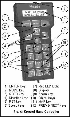
The LX200 Keypad buttons are described as follows:
1. ENTER Key
The ENTER key (1, Fig. 6) is used to select a menu file, a file option, or to edit a value. To select a file or an option, press and release the ENTER key. The LX200 will give a short beep tone and perform the action that you have requested. To edit a value, press and hold the ENTER key until a double beep tone is heard and a blinking cursor appears in the display. There are some other specific situations where the ENTER key is used. These are described in detail where necessary. From now on, the two types of presses will be called 'press' and 'press and hold'.
2. MODE Key
The MODE key (2, Fig. 6) cycles through the five modes of the LX200, and is used to exit from specific menu files.
3. GO TO Key
The GO TO key (3, Fig. 6) causes the LX200 to automatically slew to specific library entry coordinates. The GO TO key also produces a blinking cursor in the GO TO menu file of the COORDINATES/ GO TO mode, to allow new Right Ascension and Declination coordinates to be entered.
4. Direction Keys
Labeled N,S,E, and W, ( 4, Fig. 6) these four keys make the LX200 move, or slew, in a specific direction, with an option of four different speeds, explained later. During entry to change a value, the E and W keys can be used to move the blinking cursor back and forth across the LCD display, so that if an error is made during entry, it can be erased and changed.
The remaining twelve keys have multiple functions, there are up and down arrow keys and numbered keys from 0 through 9. Each one of these keys also has alternate functions listed above the arrow symbols and numbers. The ALT LED light is only visible when entering numerical data. A description of the individual keys follows:
5. Speed Keys (SLEW, FIND, CENTER, and GUIDE)
These keys (6, Fig. 6) allow you to set the rate of movement or slew speed in the drives of the LX200, as activated by the N, S, E, and W keys. The chosen rate is indicated by the speed indicator illuminated LED beside the rate key that you have pressed. The speed rates are SLEW (for the 7", 8" and 10" telescopes, it is 8 degrees per second, for the 12" telescope, it is 6° per second), FIND (2 degrees per second), CNTR (32X sidereal rate), and GUIDE (2X sidereal rate).
NOTE: All of the slew speeds will drive the LX200 in all four directions, except for GUIDE. The 2X sidereal speed in GUIDE has one difference in that it will not interrupt the Right Ascension tracking direction to make Easterly (for Northern hemisphere) or Westerly (for Southern hemisphere) adjustments; it will merely slow down the tracking drive to one half its normal speed. You will find, however, that the slower drive will move the image opposite of the tracking direction, without disturbing the smooth drive action. This performance is absolutely essential when making astrophotographs.
Also note that on DC power sources, the top speed of 8 degrees per second (7", 8" and 10" telescopes) and 6 degrees per second (12" telescopes) is slightly slower. Guiding and tracking rate speeds, are however, unaffected.
SLEW, FIND, CENTER, and GUIDE keys also have numbers listed 7, 4, 1, and 0 respectively. When editing a value, the multiple function of each of these keys is realized. SLEW and FIND are also used to set the 'fast' focus speed for the electric focuser accessory option*, while CNTR and GUIDE set the'slow' focus speed. There are other special functions for the CNTR and GUIDE keys that are discussed in the RET KEY operations.
6. RET Key
Typically used for guiding the LX200 during an astrophotograph, the RET key (5, Fig. 6) is used to change the brightness and pulse rate of the optional corded style illuminated reticle eyepiece*. Pressing either the PREV and NEXT (up and down arrow) keys while holding down the RET key, alters the reticle brightness level up or down.
When guiding on very faint stars, you may find it helpful to pulse the light from the LED so that the reticle crosshairs blink on and off. You will be able to adjust the reticle brightness as well as adjust the pulse rates. There are three pulse rates that can be used, all with a one second pulse interval. The continuous illumination control and pulse rates are set by holding down the RET key and pressing one of the following keys; GUIDE (100% on, no pulsing), CNTR (50% on, 50% off), MAP (25% on, 75% off), CNGC (10% on, 90% off).
7. FOCUS Key
The FOCUS key (9, Fig. 6) allows 2 speed electric focus control of the optional Meade #1206 Electric Focuser* (or equivalent corded electric focusers such as the Meade Model #1200A). To activate, press either the SLEW or FIND key (for fast focusing), or the CNTR or GUIDE key (for slow focusing), press and hold the FOCUS key, and then press and hold the PREV or NEXT keys for near and far focus.
8. MAP Key
The Map key (11, Fig. 6) turns on and off the red LED 'flashlight' that is located at the top of the Keypad. The deep red LED light will protect your night vision while you search for a particular accessory or examine a star chart.
9. Object Keys (M, STAR, and CNGC)
These keys (10, Fig. 6) allow direct access to the LX200's Object Library any time that you are not editing a value or setting a parameter, or selecting a file menu. Use the Object keys when you are at a "top level" of a mode. After pressing one of these keys, the Keypad's display will give a blinking cursor, allowing you to enter the catalog number for objects listed in the library (see Appendix D. 64,359-Object Library). After entry press the ENTER key. To see the entered object press the GO TO key. A brief description of the catalog key symbols are; M (Messier objects), STAR (stars and planets), and CNGC (Computerized New General Catalog).
10. PREV AND NEXT Keys
The PREV and NEXT (up and down arrow) keys (12, Fig. 6) move the display LCD arrow up and down the menu files and menu file options, so that you may choose an individual selection to enter. These keys are also used when adjusting the RET brightness range, or when activating the electric focuser. PREV and NEXT work as well to select the objects from the Object Library when using START FIND.
F. THE LX200 POWER PANEL

The power panel incorporates a power switch and LED indicators showing power on with a current ammeter to show power draw. There is also a N/S switch for Northern hemisphere and Southern hemisphere use.
The Power Panel has all of the connectors for the AC or DC power input, the DEC Motor, and the Keypad. There are connectors designed to accept optional accessories such as a CCD autoguiding camera, the optional Meade Encoders* that will update the Keypad even if you move the LX200 manually (not using the N, S, E, W keys), the optional Meade #1206 Electric Focuser*, and an illuminated reticle eyepiece*. There is even a connector for RS-232 communication that will allow you to perform every function of the Keypad from your personal computer. An illustration and a description of the LX200 Power Panel features follows:
1. ON/ OFF Switch
When the ON/ OFF Switch (7, Fig. 7) is moved to the ON position, the power light indicator, the Current Ammeter, and the Keypad all light up. You will hear the drive motors rev which momentarily pegs the Ammeter, then the drive motors shift to a slower speed which allows the RA worm gear to find its' centering position for calibrating the Smart Drive, then resuming to an even slower tracking speed. The Keypad Display reads 'Meade LX200', then the version of the software is indicated briefly before defaulting to the TELESCOPE/ OBJECT LIBRARY. Within 15 seconds, the planetary orbital calculations with their corresponding apparent sizes and magnitudes, and current stellar precession calculations are made. Every computer function is checked, and the LX200 diagnostics is complete.
2. N/S Switch
The recessed N/S Switch (8, Fig. 7) converts the LX200 for operation in the Northern or Southern hemisphere, making the drive reverse its' tracking direction. Before power up, the appropriate N or S switch position should be made, as the LX200 will not recognize a change made on the N/S switch afterwards. Use a pen or small tool to slide the switch appropriately. Be sure before you travel across the equator, that you are setting the proper + or - latitude SITE entry for your final destination.
3. Ammeter
The Ammeter display (1, Fig. 7) is a series of vertical red LED bars. Each bar that is fully lit represents 0.1 ampere (100 milli-amperes) of current draw. The LED Ammeter represents its' lowest value on the extreme left of the scale. During normal tracking speeds, the Ammeter will show about four fully lit LED bars and at times a fifth that is partially lit, indicating about 400 to 450 milliamps or 0.4 to 0.45 amps of current draw (when a slew in initiated, the ammeter will peg the scale momentarily showing the inertia load, this effect is entirely normal). The current draw information can be useful if you are trying to calculate how much battery life you will have during an observing run. As an example, if the ammeter has four bars lit, indicating 0.4 amps and you are using a 12 amp hour battery, then to know the approximate number of hours of life the battery would yield, you would divide 12 by 0.4 indicating a battery life of 30 hours.
4. DEC Motor Connector
The DEC Motor Port (11, Fig. 7) is an 8 pin phone jack connector socket, designed to accept standard 8 pin phone jack coil cords. One end of the supplied coil cord plugs in to the Power Panel and the other plugs into the DEC MOTOR socket in the right fork arm to power the declination motor.
5. CCD Connector
The CCD Port (10, Fig. 7) allows direct interface from popular aftermarket CCD autoguiding/imaging cameras with their compatible connecting cables to accomplish autoguiding for non-attended astrophotography. The CCD cameras effectively watch a star and detect slight movements. When star movements are detected, signals from the CCD electronics make drive corrections in the LX200, to bring the star to a home position.
Most CCD autoguiding/imaging cameras are supplied with a cable which is compatible with the LX200 port. If your CCD unit does not have a cable, one can be obtained from the CCD manufacturer, or you can make your own cable using the following table of information.
6. Power 12vDC Connector
The Power 12v DC connector (9, Fig. 7) is designed to accept either the AC Converter that is supplied as standard equipment with the LX200 or the DC Power Cord that is available as optional equipment. The acceptable voltage range (under load) is from 12 to 18 volts.
7. Keypad Connector
The Keypad connector (6, Fig. 7) is a 4 pin phone jack connector socket, designed to accept standard 4 pin phone jack coil cords. One end of the supplied coil cord plugs into the Keypad port, the other end plugs into the LX200 Keypad.
8. Reticle Connector
The Reticle connector (5, Fig. 7) accepts optional accessory corded, plug in style illuminated reticle eyepieces such as the Meade 12mm Illuminated Reticle Eyepiece, or the Meade Series 4000 Plössl 9mm Illuminated Reticle Eyepiece (corded style)*, to allow brightness control and on/ off pulsing rates to be set from the LX200 Keypad.
9. Focuser Connector
The Focuser connector (4, Fig. 7) accepts optional accessory corded, plug in style electric focusers such as the Meade #1206 Electric Focuser*, to allow electric focus adjustment control from the LX200 Keypad.
10. RS-232 Connector
The RS-232 connector (2, Fig. 7) allows personal computer interface to allow communications at 9600 baud to access every feature of the LX200 Keypad. In Appendix F of this manual is a wiring schematic to make your own RS-232 connector cord, a cord test program, a demonstration program, and the LX200 Command Set for writing programs. Meade Instruments supplies this information for professional programmers. Meade Instruments Corporation does not offer support or advice for writing software for the RS-232 option.
11. Aux Connector
The Auxiliary connector (3, Fig. 7) is used for the 7" Maksutov fan power.
* See the current Meade Telescope Systems and Accessories Catalog.
G. MODE FUNCTIONS
To view the separate modes within the LX200 system, press the MODE button located between the ENTER and GO TO keys at the top of the hand controller. Simple entry and editing of information in the different modes contained within the system, will customize the operation of your LX200 to perform virtually any of your observing requirements. Better still, all of the critical information such as time, location, alignment type, and many other functions are kept in memory...even with the LX200 turned off!
The type of alignment, the objects that you see, the location that you observe from, the tracking speeds of the drives, all of the clock and timing functions, the position information, and even the brightness level of the backlit Keypad are defined by the information that you give and/ or the commands that you edit, through five different modes of the LX200 computerized hand controller.
Once you have selected the desired mode, you can then select the individual file within the mode by pressing the PREV or NEXT key (up and down arrow key) in the bottom right hand portion of the hand controller, moving the LCD arrow up or down beside the file description. Although you will only be able to see two menu selections at a time in the Keypad Display, you will see more as you continue to press the PREV and NEXT keys.
When the desired file is chosen, press the ENTER key to view the file's menu. To choose an individual menu, again use the PREV or NEXT key to run the LCD arrow up or down the file's menu. To explore a menu selection, again press the ENTER key. In some modes there will be options for a file's menu selection, in others you will only enter data.
At any time that you wish to return to main file heading in a particular mode, just press MODE and it will behave as an exit key.
1. Mode One: TELESCOPE/ OBJECT LIBRARY
This is the mode that the LX200 will default to after the instrument completes its self-check, when the LX200 is first turned on. The TELESCOPE/OBJECT LIBRARY mode can be thought of as command central. It is here that we can select the way that we want the LX200 to perform mechanically, and where we can explore and select from its extensive library of stored objects.
To explore either the TELESCOPE menu file or the OBJECT LIBRARY menu file, move the LCD arrow to the appropriate selection by using the PREV or the NEXT key and press the ENTER key.
a. TELESCOPE Menu File
Below are the eleven menu selections of the TELESCOPE menu file illustrating the individual menu files and file options.
1) SITE
The SITE menu option allows you to enter up to four of your favorite viewing locations in longitude and latitude. The entered longitude and latitude is compared by the LX200's computer to your local time, GMT offset, and calendar date to accurately calculate celestial coordinates. Once entered, the information is stored in the telescope's internal memory, you need never to re-enter the same information unless you decide to change it. To enter new site information or to change an old one, refer to section D. Quick Start.
You can choose any one of the four site selections at your convenience, without the bother of entering longitude and latitude every time you use the LX200. Once the site is chosen, exit the SITE menu by pressing the MODE key.
2) ALIGN
The Align menu selection of the TELESCOPE file demonstrates the unique ability to transform the LX200 into an Altazimuth, celestial tracking telescope, a polar-equatorial celestial tracking telescope, or land spotting scope with electric Altazimuth movements within three options, which are; ALTAZ, POLAR, and LAND.
Assuming that you have already entered correct local time and your site' s latitude and longitude (refer to section D. Quick Start) you are ready to choose a particular type of alignment, by pressing the NEXT or PREV key to run the LCD arrow beside the desired option of ALTAZ, POLAR, or LAND, and then pressing the ENTER key. The display will then give you specific instructions from this point that will literally walk you through the chosen alignment type.
a) ALTAZ
The 2-Star initialization routines provide three options for aligning the LX200 telescope when in the ALTAZ mode. (Note: The 2-Star initialization routines only apply to the ALTAZ alignment mode.
The first and second options require that you have entered the SITE and TIME information, and the third option can be used when the SITE information is not known or has not been entered into the LX200's memory.
a. 1-Star with Known SITE
After selecting the SITE location (1-4), move to the ALIGN menu (see steps 5-9).
When you select the ALTAZ alignment mode, the display will give you two options: 1-Star or 2-Star alignment. If you select the 1-Star alignment (by pressing the "1" key), the alignment routine is exactly the same as the procedure described earlier.
b. 2-Star at Known SITE
To use the 2-Star alignment procedure at a known site, follow these steps:
(1) Select the 2-Star alignment (by pressing the "2" key); the Keypad display will prompt you to level the tripod. This leveling step requires a rough level only and, unlike the 1-Star alignment routine, does not affect the pointing accuracy of the telescope. (See Section d. below for a summary of the differences in telescope operation when selecting each of the three alignment procedures.)
(2) After leveling the base and pressing ENTER, follow the Keypad display prompts to select the first alignment star. Slew to that star using the N, S, E, W keys. (3) Follow the Keypad display prompts to choose and center the the second alignment star. Be sure to use the Keypad to slew to the second star. After pressing the ENTER key in the last step, the Keypad display should show the TELESCOPE / OBJECT LIBRARY screen.
The LX200 calculates the distance between the two stars that you chose in the alignment steps and compares this to the distance that you actually slewed the telescope. This is a check to be sure you centered the correct stars during the alignment steps. Should the LX200 discover a discrepancy, the Keypad will display an "Align Mismatch - Check Stars" message. If you get this message after aligning the telescope, check that you are using the correct stars and align again.
Whenever using either of the two 2-Star alignment procedures (at a known SITE or at an UNKNOWN SITE), choosing the proper two stars will determine the pointing accuracy of the telescope. Choose two stars that are not too close together--try to use stars that are at least 90° apart. Do not use Polaris as one of the stars because RA changes very fast at the Pole and minor centering errors can translate to large RA pointing errors. Also, avoid stars near the zenith (straight up) since azimuth changes very fast in this area. Generally speaking, choosing two stars as far apart as possible will yield very accurate pointing.
c. Unknown SITE
To use the LX200 telescope at an unknown location, use the following procedure:
(1) Select site #5 (UNKNOWN) from the SITE menu. (Note: This site cannot be edited like site numbers 1-4 as described on steps 4-10.)
(2) Follow the Keypad display prompts to select and center the two alignment stars.
As described above, the LX200 will check the accuracy of the two stars and give the "Align Mismatch - Check Stars" message if it detects an error.
d. Which Alignment Method To Use?
Each of the three methods described above have advantages and disadvantages. The following table summarizes these properties.
 |
| Table 4: Alignment Methods |
|---|
b) POLAR
POLAR allows you to use the LX200 mounted on its' optional Equatorial Wedge (see Appendix A) for long exposure astrophotography as well as visual work. With the LX200 powered up, the POLAR file option selected, the Field Tripod leveled, the telescope should be adjusted so that the Declination Setting Circle (3, Fig. 3) is set to 90 degrees (see Fig. 4), and to the 00 hour angle (HA) in Right Ascension (in this position, the Viewfinder (Fig. 3) is up-side down, the R.A. Pointer (9, Fig. 3), the 00 line of the R.A. Setting Circle (10, Fig. 3), and the Hour Angle Pointer (16, Fig. 3) match up), you are ready to start. (If you do not start at the 00 H.A. position, the telescope it will point to the ground instead of the sky, when the Keypad display chooses its' second star.) Press the ENTER key and the LX200 will determine and slew to the precise off-set of the pole star in Declination and Right Ascension.
At this point you need only aim the instrument at the pole star (see Appendix B, section 3. Precise Polar Alignment if the pole star is not visible) and center it in the eyepiece field using only the Altitude and Azimuth adjustments on the Equatorial Wedge (see Appendix A). Once done, you again press the ENTER key and the LX200 will choose and slew to a very bright star that is overhead and can usually be seen in the field of view of the viewfinder. At this point, center the bright star using only the Right Ascension and Declination adjustments of the telescope (either manually by loosening the locks only or electrically), then press ENTER. You can now access every every function of the LX200 including the Smart Drive.
c) Refined Polar Alignment
Astrophotographers routinely require polar alignments of the highest accuracy for the finest guiding characteristics. Your initial polar alignment can be refined by using the LX200's electronics by using a slightly different method in POLAR menu option. The routine outlined below should be performed in two or three 15 minute intervals. At each interval the telescope will slew to the area where the pole star should be centered in the optics. You may find that the pole star is somewhat off-center in the eyepiece showing the alignment error that may have been made during your initial setup. Re-center the pole star during each interval exercise using the Equatorial Wedge adjustments only (see Appendix A) in Altitude and Azimuth, then follow the rest of the routine.
Return to the POLAR menu option in the TELESCOPE mode and press the ENTER key.
Ignore the Keypad display instructions to return the telescope to 90 degrees in Declination and 00 HA. Instead, press the GOTO key and the LX200 will slew to the calculated position of where the pole star should be.
Re-center the pole star in the field of view in the eyepiece using only the adjustments on the Equatorial Wedge (see Appendix A) in Altitude and Azimuth.
Press the ENTER key, and the LX200 will once again slew to a bright star overhead. Center this star using the N,S,E, or W keys and press ENTER. Note: Pressing the MODE key at any point in the alignment routine will abort the routine and exit to the top menu.
After each 15 minute interval you will find that the pole star becomes more accurately centered each time. You can repeat the intervals as often as you like to obtain the highest accuracy. An optional illuminated reticle crosshair eyepiece* makes the job of centering the star easy.
There may be situations when it is impossible to see the pole star due to something blocking your line of sight. In such an occasion, just press the ENTER key next to the POLAR option so that it has a check next to it and follow the Precise Polar Alignment instructions in Appendix B to this manual. You will require the use of an illuminated reticle crosshair eyepiece* to complete the task. Once finished, follow the steps in The Permanently Mounted, Polar Aligned LX200 section to access the Object Library.
d) The Permanently Mounted, Polar Aligned LX200
For those who will permanently mount the LX200 in an observatory, or wish to use the already polar aligned telescope for several nights in succession, it is recommended that a high-precision polar alignment be made with one of the methods described above. Once done, however, you need not bother yourself to go through a polar alignment routine on successive nights, provided that you do not move the instrument's Equatorial Wedge or Field Tripod, to access the Object Library and enjoy near perfect tracking.
To bypass the polar alignment sequence, follow the steps outlined below:
1. Return to the POLAR menu option and place a check next to it by pressing the ENTER key.
2. Then directly enter the catalog number of an object that you are familiar with in the sky by pressing the M, STAR, or CNGC key (see Appendix D. for a listing of the 64,359 Object Library) and press the ENTER key again.
3. Manually center the familiar object in the eyepiece of the telescope.
4. Press and hold the ENTER key until the display reads 'Coordinates matched'.
5. You have now synchronized the Object Library and the LX200 will correctly access every other object in the sky.
e) LAND
The LAND menu option transforms the ALTAZ (Altazimuth) mounted LX200 into an electric slewing spotting scope. In this mode, continuous tracking is canceled and all of the celestial pertinent modes and menus are non-functional, showing lower case lettering in the displays and a beep tone if you try to enter one of them.
The LX200 will slew at any one of the four speeds of SLEW, FIND, CNTR, and GUIDE as activated by pressing the appropriately marked keys on the extreme left of the Keypad display. Altazimuth coordinate readings can still be displayed in the coordinates mode (see MODE 2 in this section). Refer to section D. Quick Start in this manual for the LAND menu option, for full operating procedures. You will also find that the addition of the Meade #928 45 Degree Erect Image Prism or the Meade #924 Porro Prism* instead of the standard supplied star diagonal prism, will give the normal right side up and left to right views that you are accustomed to when using a spotting scope.
3) SMART
The SMART menu file controls the Smart Drive and allows you to train almost all of the periodic error from the Right Ascension drive worm gear (errors induced by tiny gear imperfections that tend to slightly speed up or slow down the drive tracking speed, that occur in a regular 8 minute pattern, or for every rotation of the worm) for greatly enhancing the tracking characteristics or the amount of East and West drift of your LX200. This greatly simplifies guiding during astrophotography. The menu also has provisions for correcting Declination drift. Smart Drive will retain the training given to the R/A drive, even after the telescope is turned off. There is of course a way to erase any training given to it at your command.
The SMART menu has five options. They are; LEARN, UPDATE, ERASE, DEC LEARN, and DEC CORRECT. To use the Smart Drive, the LX200 must be mounted with the optional Equatorial Wedge (see Appendix A), equipped with an illuminated reticle eyepiece*, and used in the POLAR align menu selection. Be sure to train the Smart Drive in the 60.1 Hz Quartz setting that the LX200 will be automatically set at power up. Thereafter, you can adjust this setting in the TIMER/ FREQ mode and still enjoy the periodic error correction.
Once a polar alignment has been completed, your LX200 will point to a bright star overhead that will be near the Celestial Equator. This will be a good star to train the Smart Drive on. You can of course, move to another star just as long as you are near 0 degrees in declination and more or less overhead in Right Ascension. Now is good time to set the brightness and/ or the pulse rate (see section E. The LX200 Keypad) of the illuminated reticle on the guide star and practice guiding for a few minutes.
To actually begin training the Smart Drive, move the LCD arrow to LEARN by using the PREV or NEXT key and press ENTER. There will be numbers that will appear next to the LEARN display, that will begin counting down to zero. The highest number that can appear is 240. The period of the worm is eight minutes and the number represents a sector of the worm wheel which will change to the next lower digit every two seconds. As the Keypad display approaches sector 5, an alarm will alert you that training is about to commence. At this point try to keep the star on the same location of the crosshair during the eight minute training sequence by pressing the N,S,E, and W keys. After eight minutes, the training is over and Smart Drive will play back your drive corrections automatically, dramatically improving the R.A. drive tracking characteristics.
If you wish to further refine the accuracy, move the LCD arrow to UPDATE and press ENTER and follow the same instructions as above. This can be done in UPDATE as many times as you wish. With each training the Smart Drive will average your training sequences.
If you find that you have made a mistake in training (e.g. pushed E instead of W when you should have), you can eliminate the memory by moving the LCD arrow to ERASE and press ENTER.
A star that drifts consistently North or South during guiding, can also be corrected for. Move the LCD arrow to DEC LEARN and press ENTER. Begin making drive corrections immediately by pressing any of the direction (N, S, E, W) keys to keep the star on the crosshair of the guiding eyepiece. It is suggested that you train in DEC LEARN for at least half of your intended exposure time for an astrophoto. The longer that you train, the more accurate the DEC LEARN will be. Once the desired time is finished, press ENTER and the training will cease. The Smart Drive will then determine how many key pushes that you gave in N and S and choose the direction based from which direction received more commands. It then averages the time between key pushes in the chosen direction. In this way, the Smart Drive can correct for Declination drift (should your polar alignment be slightly off), or will allow you to more precisely guide on non-stellar objects, such as comets, asteroids, etc.
To play back your DEC LEARN training, move the LCD arrow to DEC CORRECT and press ENTER. To halt the play back press ENTER again. To erase the DEC LEARN training, either move the LCD arrow back to DEC LEARN and press ENTER twice or turn the LX200 off.
4) 12/24 HR
The 12/24 HR menu selection of the TELESCOPE file simply toggles between a twelve and twenty-four hour display of local time in the time mode.
To toggle between 12 and 24 hours displays, move the LCD arrow to 12/24HR and press ENTER. To return to the original setting, press ENTER again.
5) HELP
The HELP menu selection of the TELESCOPE file is an electronic mini-manual that will briefly describe the function of each command key on the LX200 Keypad.
To use this menu, move the LCD arrow with the PREV or NEXT key to HELP and press ENTER. To read the lines of text, use the PREV and NEXT keys. To exit, press MODE.
6) REVERSE NS
The REVERSE NS menu seletion of the TELESCOPE file reverses the direction of the telescope in North and South movements (e.g. when you press the N key the scope will move South or down instead of North or up). This is especially useful during some guiding applications in imaging and observing.
To use the REVERSE NS menu, move the LCD arrow to REVERSE NS and press ENTER. If you wish to return the direction commands to the original setting, press ENTER again.
7) REVERSE EW
The REVERSE EW menu selection of the TELESCOPE file reverses the direction of the telescope in East and West movements (e.g. when the W key is pressed, the telescope moves East). This is particularly useful during some guiding applications in imaging and guiding.
To use the REVERSE EW menu, move the LCD arrow to REVERSE EW and press ENTER. If you wish to return the direction commands to the original setting, press ENTER again.
8) BALANCE
When adding optional equipment to the LX200, like a heavy camera or Dewshield, it is often necessary to rebalance the telescope using the Meade #1401 (for 8" LX200's), #1402 (for 10" LX200's) , or #1403 (for 12" LX200's) Tube Balance Weight Systems.
Selecting option #8 from the TELESCOPE menu moves the LX200 telescope rapidly up and down in Declination. This provides an easy way to determine when the telescope is balanced in the Declination axis. (Remember, loosening the Dec. lock to check the balance will cause the LX200 to lose alignment.)
When the telescope is out of balance, the LX200 will draw more current when slewing in the "heavy" direction. Also, the Declination motor will sound different.
After selecting option #8, watch the Ammeter and listen to the Declination motor to determine when the LX200 is balanced.
9) HP (High-Precision Pointing)
The High-Precision Pointing (HP) feature of Meade LX200 Schmidt-Cassegrain telescopes allows for very precise pointing of the telescope. By incorporating the unique LX200 SYNC command, 0.3 arc-sec resolution encoders, and high-speed DC servo motors, observers can now place objects in the telescope's field of view with 1 arc-minute or better pointing accuracy, making critical image placement applications, such as CCD imaging, possible.
a) LX200 Pointing Accuracy
Normal telescope pointing accuracy is better than 5 arc-minutes when doing a casual alignment, which is more than accurate enough for many observing applications. (A "casual" alignment is one that uses the UNKNOWN SITE or one that is done without the use of a reticle eyepiece to EXACTLY center the alignment stars.) This type of alignment will put objects into the field of view of most eyepieces and is more than adequate for almost any visual observing application.
A "critical" alignment will improve the pointing accuracy of the telescope to 2 arc-minutes or better. This type of alignment requires accurate SITE information, time, date, proper selection of the two alignment stars, and a reticle eyepiece to exactly center the alignment stars. These steps generally require only a few extra seconds to accomplish, and improve the telescope's positioning by a substantial amount. Using the "critical" alignment will provide telescope positioning suitable for all but the most demanding pointing applications - including CCD imaging with larger chip cameras, like the Meade Pictor 416 and Pictor 1616 CCD cameras.
The HP feature increases the pointing accuracy of the LX200 to 1 arc-minute or better and also requires the "critical" alignment procedure described above. This alignment procedure will yield the best pointing accuracy possible, placing images of objects onto the active area of the even the smallest CCD cameras available.
It should be stressed that for most applications, using the HP feature is NOT required to get maximum enjoyment out of the telescope. For an evening of simple visual observations, the "casual" alignment is all that is required. Don't let the pointing precision of the telescope become more important than the fun of observing the night sky!
b) Using HP
The High-Precision Pointing mode requires the "critical" alignment, described above, to maximize the telescope's pointing ability. The LX200 default condition is with HP disabled. To activate the HP mode, select the "high-precision" option from the TELESCOPE menu (option #9). When selected, "HIGH-PRECISION" will change to all upper case letters.
When HP is active, the LX200 automatically does several things whenever a GOTO is initiated.
1. HP will search the alignment star database and find the three closest stars to the object (or position) entered. This process takes about 10 seconds and the keypad displays:
" Searching ...... "
2. The telescope will slew to the nearest alignment star. These are all bright (brighter than 3rd magnitude) stars and far enough apart to insure that there will only be one in the field of view.
3. The keypad display will display:
" then press GOTO."
Using a reticle eyepiece, center the star in the field of view. (Or center the star on the CCD chip if using a CCD camera.) Press GOTO when the star is centered.
Note: If this star is not in the field of view or if it is obstructed by a land object, the other two stars are available. Use the PREV and NEXT keys to cycle through the three closest stars.
4. The telescope will slew to the selected object or position.
10) SLEW RATE
Option #10 in the TELESCOPE menu is for changing the slew rate of the LX200 telescope. Slowing down the slew rate will result in less noise as the telescope moves and will also use a little less power. To change the slew rate, follow these steps:
1. Press the MODE key on the Keypad until the TELESCOPE / OBJECT LIBRARY menu appears on the display. The cursor should be next to the TELESCOPE option - if not, then press the PREV key to move the cursor up one space.
2. Press ENTER to select the TELESCOPE functions.
3. Press the PREV or NEXT keys to move the cursor to option #10: SLEW RATE. On the right hand part of the display, the number 8 is displayed (6 is displayed on Version 4.34 for 12" LX200 telescopes). This represents the current slew rate in degrees per second.
4. Press the ENTER key to change the slew rate. Each successive ENTER key press increments the slew rate by 1 degree per second.
5. After setting the desired rate, press the MODE key to return to the TELESCOPE / OBJECT LIBRARY menu.
Note: The slew rate is NOT stored in permanent memory and needs to be reset each time the telescope is powered up. The default slew rate is 8 degrees per second on Ver. 3.30 and 6 degrees per second on Ver. 4.34.
11) DEC. BACKLASH COMPENSATION
When taking long exposure astrophotographs, it is necessary to "guide" the photograph to make sure the telescope is tracking perfectly, otherwise stars will appear as ovals instead of pinpoints. This is done by setting the LX200 Keypad to the GUIDE speed, monitoring the star location (e.g. with an off-axis guider), and making small corrections to the telescope position by using the N, S, E, and W keys.
When making these corrections, the R.A. motor will speed up or slow down (by pressing the "E" and "W" keys). The Declination motor, however, when activated (by pressing the "N" and "S" keys) will actually stop and reverse direction. Because of backlash in the Declination motor gearbox, there will be a few seconds delay before the telescope begins to move when reversing direction.
The Dec. backlash feature compensates for the Dec. motor gearbox backlash and provides instant telescope movement when the motor direction is reversed. (Note: this feature is only available in the POLAR mode.)To program the Dec. backlash, use the following procedure:
1. Move to option #11 from the TELESCOPE menu. The Keypad display will show:
The "00" in the display shows the number of arc-seconds of backlash the LX200 is set to compensate for (the default setting is 0 arc-seconds).
2. While observing a star at high power, time the Declination movement delay when reversing the motor directions (by pressing the "N" and "S" keys). Typical values are 2 to 4 seconds.
3. The GUIDE speed for the Declination motor is 15 arc-seconds per second. Therefore, multiply the number of seconds delay by 15.
4. Press and hold the ENTER key for 1 second. The Keypad will beep and a blinking cursor will appear on the Keypad display. Enter the number determined in step 3, above. Press ENTER when the number is entered.
5. Check the time delay as described in Step 2, above. If there is still a time delay, then increase the compensation number. If there is a slight jump when reversing direction, then the number is too large.
When the compensation number is correct, the LX200 telescope will move almost instantly when reversing the direction in Declination. This number is stored in permanent memory and should never need to be set again.
b. OBJECT LIBRARY Menu File
The OBJECT LIBRARY menu file is the other half of the TELESCOPE/OBJECT LIBRARY mode. With it you can become a tourist of the sky, or conduct research surveys of the 64,359 objects. The LX200 Object Library is accessible in the most results-getting, user friendly system ever designed for observers and astrophotographers.
The position epoch of these objects is for real time, updated every time you turn on your LX200. Even the planet's positions have their orbits calculated! This not only qualifies the LX200 as the most accurate integrated object library available, it will never require updated software for precession of the stars or planetary orbital changes.
There are three primary ways to use the Object Library. You can directly access the library by using the M, STAR, or CNGC keys (see section E. The LX200 Keypad) and entering a specific catalog number, the START FIND option can be used to logically find objects in organized strips of the sky that can be custom tailored to only show the objects you wish to see with a selection of object types, size brightness, etc., or you can scan the sky and have the Object Library tell you what is in the field of view in the eyepiece by using the FIELD option. Below is a description of the four OBJECT LIBRARY menu files and file options:
To access the OBJECT LIBRARY menu file, move the LCD arrow to the OBJECT LIBRARY display by pressing the PREV or NEXT key while in the TELESCOPE/ OBJECT LIBRARY mode and press the ENTER key. Now you can access the four menu selections within the OBJECT LIBRARY by moving the LCD arrow to the desired menu selection by using the PREV or NEXT keys and doing the following steps.
1) OBJECT INFO
Press the ENTER key to read the type, brightness, size, and quality. Press ENTER again to read the coordinates. Press ENTER once more to determine how far off the telescope is pointing from the entered object (this is displayed in LCD bars, each bar is ten degrees, or if it is on the object, no bars). This same information can also be accessed at any time by pressing the ENTER key for any object entered by the M, STAR, or CNGC keys. Press MODE to exit to the main menu file.
2) START FIND
The START FIND option resources the CNGC objects within the Object Library and begins a logical search starting wherever the telescope is positioned when activated. To cover the entire visible sky it will make 31 strip divisions about 12 degrees wide, moving from West to East, from the North Pole to the South Pole, then South to North. Once it has found all of the CNGC objects it will repeat its sequence until new objects are visible.
Press the ENTER key and the hand control will display the first object in its finding sequence. This first object is selected by the LX200, based off of where the instrument is pointing in the sky when you entered START FIND. To point your LX200 to the object displayed, press the GO TO key and it will slew to the object.
While in the START FIND option, you can either choose the next object in line or skip it as you wish. In order to find the next object in sequence, press the NEXT key, and the display will read the new CNGC object. If you do not wish to view this object, you can skip it by pressing NEXT again. If you wish to return to a previously viewed object, press the PREV key until the desired catalog number is displayed and press the GO TO key. If you have set some limitations in the PARAMETERS option, it will only find those objects within your chosen confines.
If you find that the object is not well centered in the eyepiece after executing a GO TO (due to poor leveling, improper time input, or errors in site location), center the object; then press and hold the ENTER key until the display reads "Coordinates Matched." This feature in essence synchronizes the LX200 for an area of the sky, so that the next object (if the leveling, time input, or site location information is not corrected) will be better centered, provided it is not too far away from the object that you matched coordinates to.
To exit the START FIND menu selection (and cease its operation) to the main menu, press the MODE key.
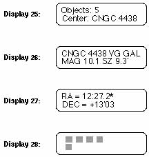
3) FIELD
Press the ENTER key to identify objects in the field of view of the telescope. The LX200 will display the object centered in the eyepiece field, and how many other NGC objects are in the field at the same time (defined by the RADIUS parameter setting) as shown in Display 25:
Press the ENTER button to reveal information about the object as shown in Display 26:
Display 26 is interpreted; COMPUTERIZED NEW GENERAL CATALOG #4438, VERY GOOD, GALAXY, MAGNITUDE 10.1, SIZE (in arc minutes) 9.3'. Press ENTER again to read the coordinate location of the object (notice the * legend next to RA coordinate number, it indicates the catalog coordinates of the object, not necessarily where the telescope is pointing) as shown in Display 27:
Press ENTER once more to see physically how far your telescope will have to move to acquire the object entered. The display will show LED bars, each bar represents ten degrees of movement as shown in Display 28:
If you are centered on the object already, such as if you are in the FIELD menu selection, or if you have already made a GO TO command in one of the other methods for finding an object, the above display will be blank.
To review any of the data of an object, continue to press the ENTER button until the desired field appears. You can use the above commands at any time that you have an object entered in the Keypad, while directly entering in specific objects by pressing the M, STAR, or CNGC keys, in the START FIND menu selection, the OBJECT INFORMATION menu selection, or the FIELD menu selection.
4) PARAMETERS
It is here that you can edit the Press ENTER to find eight options which can be reviewed by scrolling through this menu selection by using the PREV or NEXT key. To edit one of the options, move the arrow to the desired option and press and hold the ENTER key until a double beep is heard and a blinking cursor appears (except in the BETTER option) Where numerical values are to be input, simply type them in from the Keypad. If you make a mistake, you can move the cursor backward using the W key, then re-enter the data. To exit to the main option menu, press the ENTER key once again. A description of the eight options and how to set them is below:
a) TYPE GPDCO
This menu file option allows you to select the type of CNGC objects that you wish to locate. The symbols GPDCO represent:
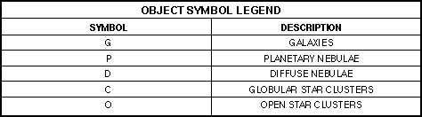 |
| Table 5: Object Symbol Legend |
|---|
Initially, the blinking cursor appears over the G symbol. If you decide not to look for galaxies, press the NEXT key and the symbol will change from an upper case letter (G) to a lower case letter (g), to deselect the GALAXIES category. If you wish to leave GALAXIES selected, then move the blinking cursor over to one of the other category symbols by pressing the W or E key on the Keypad. You can then deselect the undesired categories.
If you wish to recall a category symbol, move the blinking cursor over the symbol and press the PREV key. After your selections are made, press ENTER.
b) BETTER
The BETTER menu file option allows you to define the visual object quality range. At power up, the range is set at the bottom of the scale on VP, when using the START FIND menu selection, it will select all objects that are very poor through super or what could be considered an "ALL" setting. The object quality symbols are:
 |
| Table 6: Quality Symbol Legend |
|---|
If you wish to define the visual object quality range to very good and better, press the ENTER key until the symbol VG is displayed. From the VP setting to VG requires three ENTER key presses. The LX200 will now select objects that look Very Good through Super.
c) HIGHER
The Higher menu file option sets the horizon setting for the telescope. At power up, the setting is 00 degrees, which assumes that you have an unobstructed line-of-site to the horizon in every direction. If, however, there are things obstructing a level horizon, or if the sky quality is poor due to haze or light pollution, you can set an artificial horizon level so that your LX200 will not try to find objects below your setting.
Enter the number of degrees above the horizon that will clear the obstructions in the sky. To roughly judge how many degrees the obstruction is taking up of the sky, merely hold your fist at arm's length. Each fist diameter is approximately 5 degrees. So, if a tree is three fists high, you would make a setting of 15 degrees in the HIGHER setting. Once the setting is finalized, press ENTER.
d) LARGER
The LARGER menu file option allows settings of the lower apparent size limit of the objects you wish to see. At power up it is set to 000' (arc minutes). In order to make a decision as to the size limits that you may impose, it helps to have a clear understanding of exactly what an arc minute of sky is. A good example is the apparent size of the Moon, which could be expressed as 1/2 of a degree, 30 arc minutes, or 1800 arc seconds. Each arc minute is 60 arc seconds, and there are 60 arc minutes for each degree of sky.
Some beginning observers have a tough time discerning objects less than about 1 arc minute in size unless it is a double star or a planet. Astrophotographers and those involved with CCD imaging may want to set a higher value based off of desired image scale coverage that would be most impressive with different films or types of CCD cameras. Enter the new value in arc minutes, then press ENTER to exit to the option file.
e) SMALLER
The SMALLER menu file option is the upper size object limit. At power up the setting is for 200' arc minutes or 3.33 degrees. This setting is high enough to cover the largest objects in the OBJECT LIBRARY. You may want to lower the value because of true field-of-view limitations of a particular eyepiece (see the RADIUS parameter option for calculating true field).
Other reasons for limiting the value in SMALLER is for astrophotographic or CCD imaging requirements where we don't want the object to exceed the imaging area of the film or the CCD chip.
f) BRIGHTER
The lower brightness limits based on stellar magnitude can be limited in the BRIGHTER menu file option. At power up, the magnitude value is set to a very faint level of +20.0.
You may want to adjust the magnitude level to a brighter value starting at perhaps the limiting visual magnitude of your LX200, which is approximately 14.0 for an 8" and 14.5 for a 10". If you are making astrophotographs, the limiting magnitudes are about 16.5 and 17 for the eight and ten inch instruments respectively. Sky conditions also greatly affect the limiting magnitude due to atmospheric haze, high clouds, light pollution, or combinations thereof.
g) FAINTER
The upper level of brightness may also be adjusted with the FAINTER menu file option, although you may find few applications for limiting it to a lower value.
h) RADIUS
The RADIUS value sets the boundaries of what and how many objects the LX200 recognizes is in a given eyepiece while in the FIELD menu selection. At power up the RADIUS menu file option is set to 15 arc minutes, the radius of 1/2 a degree (30 arc minutes), which is about the proper setting for a 26mm eyepiece used in an 8" f/10 LX200.
To calculate the true field of an eyepiece in the telescope, first divide the focal length of the telescope (e.g. 2000mm for an 8" f/10) by the focal length of the eyepiece (the standard supplied eyepiece is a 26mm Super Plössl, 2000 divided by 26 equals 77X magnification). Then find the apparent field of the eyepiece (which is 52 degrees for the 26mm Super Plössl) and divide it by the magnification (52 divided by 77 equals .67 degrees, multiplied by 60 equals 40.2 arc minutes).
To get the radius of the true field of view, divide the true field by 2. In the case of the above equation, 40.2 arc minutes divided by 2 equals 20.1 arc minutes.
2. Mode Two: COORDINATES/ GO TO
Mode two allows you to see where you have pointed the LX200 in two celestial coordinate formats, either Right Ascension and Declination or Altazimuth. Also in this mode you can enter new Right Ascension and Declination coordinates for any sky position, perhaps to locate objects not in the LX200 library such as comets or asteroids and have your telescope slew to the new coordinates.

a. Coordinates Menu File
You will at first see the RA = and DEC = coordinates of where the telescope is pointing. If you move the LX200 with the N,S,W,or E keys, the coordinates display will immediately update the new position in Right Ascension and Declination.
You can also display computed information of the Altazimuth coordinates (ALT = and AZ =) by pressing the ENTER key. To return to RA = and DEC =, press the ENTER key again.
The RA = display is broken down into hours, minutes, and seconds, and the DEC = display is broken down into + for North Declination and - for South Declination into degrees, minutes and seconds as shown in Display 29:
If you have made an ALTAZ style of alignment, the ALT = and AZ = coordinate display is formatted so that 0 degrees Azimuth (AZ =) is due South that increases to up to 359 degrees, 59 minutes, and 59 seconds moving clockwise, or from due South moving Westerly. Altitude (ALT =) is formatted so that straight overhead is +90. degrees and 00 minutes, decreasing to +00. degrees, 00 minutes, and 00 seconds as you move the telescope level with the horizon, and then as the LX200 moves below +00:00:00 it will give minus Altitude readings. The Altazimuth coordinate display is shown in Display 30:
While in ALTAZ, you will find during slewing in one direction, that both the RA= and DEC= display will change at the same time, while the ALT= and the AZ= display will only change in the direction that the telescope is being slewed. It is also important to note that only the Declination Setting Circle (3, Fig. 3) will give a correct reading. The R.A. Setting Circle (10, Fig. 3) will only give correct readings in the POLAR setting (see Appendix B: Equatorial Use).
b. GO TO Menu Option
The GO TO menu option, allows you to enter new Right Ascension and Declination coordinates of any object in the sky, so that the LX200 will slew to the new position. With this ability, your LX200 knows no bounds, any celestial object, including comets, asteroids, etc. are easily found, provided you have accurate coordinate data to refer to.
To enter a new pointing position in Right Ascension and Declination, press the GO TO key and a double beep will be heard followed by a blinking cursor that will appear over the RA = coordinate numbers. At this point, type in the new Right Ascension coordinate numbers, then press the ENTER key. You will then notice that the blinking cursor is over the DEC = coordinate numbers. Enter the new Declination coordinate numbers, then press the ENTER key and the LX200 will slew to the new coordinate position.
If you need to enter a minus Declination setting, move the blinking cursor over the + symbol with the W key and then press the NEXT key to get the - (minus) symbol, then move the blinking cursor to the first number with the E key and enter the new coordinate numbers. If you are already at a minus (-) Declination setting and wish to enter a plus (+) declination setting, follow the same instructions as above but press the PREV key instead to get the + symbol.
c. Slew To ALTAZ Coordinates
This feature is similar to the GO TO Right Ascension and Declination coordinates option. It allows you to directly enter the altitude and azimuth coordinates and slew to this position. This also can be used in the LAND mode, allowing the automatic acquisition of land objects for commercial applications. (Note: This feature is not available in the POLAR mode.)
To slew to ALTAZ coordinates, follow these steps:
1. Go to the ALTAZ display.
2. Press the GO TO key on the Keypad. You will hear a quick double beep, and a blinking cursor will appear in the ALT display line on the Keypad display.
3. Key in the desired ALT position and hit the ENTER key. The blinking cursor will move to the AZ line.
4. Key in the desired AZ position. When the ENTER key is pressed, the telescope will slew to the new position.
3. Mode Three: CLOCK/ CALENDAR
The continuously operating clock and calendar is the life pulse of your LX200. At power up, the telescope's accurate sidereal clock automatically allows the system computer to make orbital calculations of the planets, and correct stellar precession for superior pointing ability.
Your accurate initial input of local time and date, with its' long-life lithium battery back-up, need not be re-entered every time you use the LX200, thus enhancing the user friendly aspects of the instrument.
To set the local time and date and to enter the correct GMT offset, refer to section D. QUICK START, of this manual. Be sure to use your local hour setting appropriately in either 12 hour or 24 hour format as predetermined by the 12/24 HOUR TELESCOPE menu file option.
The long-life lithium battery (Panasonic CR2032 3 volt or Duracell DL2032B) is stored behind the Power Panel of the Drive Base. See Appendix E. in this manual for battery replacement information.
4. Mode Four: TIMER/ FREQ
a. TIMER = Menu Option
The TIMER = menu option is for accurately timing different observing or imaging tasks for up to twelve hours long. Counting down to zero, in the hours, minutes, and seconds format, it will give a pleasant beeping tone to notify you that the time is up.
To set the TIMER, move the LCD arrow to TIMER= 00:00:00. Then press and hold the ENTER key to get the double beep tone and the blinking cursor. Enter the number of hours, minutes, and seconds that you require. If you need to correct an error in entry, use the E and W keys to move the blinking cursor and then type in the correct information. After entry, press the ENTER key again and the cursor will eliminate. When you are ready to start your time count-down, press the ENTER key once more. To pause the count-down press ENTER again, and then again to resume.
If you merely want an automatic 12 hour count-down, just press the ENTER key without holding. Then press ENTER to count-down.
b. FREQ= Menu File
FREQ= (Frequency) allows you to adjust the tracking speeds (not slew speeds) of the LX200 digitally in tenths of a hertz from 56.4 Hz to 60.1 Hz, so that you can match virtually every celestial motion in the sky. Some popular drive rate settings are:
 |
| Table 7: Drive Rate Settings |
|---|
Note: If you have trained the Smart Drive in the 60.1 Hz Q setting (see SMART menu file in this section), you will find that Smart Drive will still give periodic error corrections in all of the other frequency settings.
There are three menu file options in FREQ=. To see or set the options, move the LCD arrow to FREQ= and press the ENTER key. At power up, the FREQ= default is the 60.1Hz Q setting. The quartz rate is precisely fixed and cannot be altered. To choose a rate other than the quartz setting, press the ENTER key to see 60.1 M and then again to see 60.1 M with the up and down LCD arrow. These two menu file options can adjust the tracking speeds. The adjustment techniques are described below:

Display 31 shows the manual rate menu file option that can be adjusted by pressing and holding the ENTER key to get the double beep tone and the blinking cursor. Type in the new rate, then when finished, press the ENTER key again.
Display 32 shows the menu file option allows you to step the drive tracking frequency setting in tenths of a hertz, by using the PREV and NEXT (up and down arrow) keys. This is a convenient feature if you are trying to match the precise speed of a planet, comet, or any other non-stellar object. To exit this option, press the MODE key.
5. Mode Five: KEYPAD OFF/ BRIGHTNESS ADJUST
In order to see very faint objects, it will sometimes be necessary to either dim or completely turn off the Keypad red LED backlighting. To do so press the MODE button until the display goes blank. This is the OFF option.
To set the Keypad brightness, press the ENTER button and adjust the brightness to your satisfaction with the PREV and NEXT keys. To exit, press the MODE key.
Note: The backlighting is done by edge lighting a plastic light bar underneath the Keypad. Four LED's are used and do not give a perfectly even backlighting of the keys as keys closer to a LED will be a little brighter than those keys further away.
H. MAGNIFICATION AND FIELD OF VIEW
1. Magnifications
The magnification, or power, of the telescope depends on two optional characteristics: the focal length of the main telescope and the focal length of the eyepiece used during a particular observation. For example, the focal length of the LX200 7" f/15 is fixed at 2670mm, teh focal length of the LX200 8" f/10 telescope is fixed at 2000mm; the focal length of the 10" f/10 telescope is fixed at 2500mm; and the focal length of the 12" f/10 telescope is fixed at 3048mm. To calculate the power in use with a particular eyepiece, divide the focal length of the eyepiece into the focal length of the main telescope. For example, using the SP 26mm eyepiece supplied with the 8" f/10, the power is calculated as follows:
The type of eyepiece (whether "MA" Modified Achromatic, "OR" Orthoscopic, "SP" Super Plössl, etc.) has no bearing on magnifying power but does affect such optical characteristics as field of view, flatness of field and color correction.
The maximum practical magnification is determined by the nature of the object being observed and, most importantly, by the prevailing atmospheric conditions. Under very steady atmospheric "seeing," the 7" LX200 may be used at powers up to about 450X on astronomical objects, the 8" LX200 may be used at powers up to about 500X, the 10" LX200 up to about 600X and the 12" up to about 750X. Generally, however, lower powers of perhaps 250X to 350X will be the maximum permissible, consistent with high image resolution. When unsteady air conditions prevail (as witnessed by rapid "twinkling" of the stars), extremely high-power eyepieces result in "empty magnification," where the object detail observed is actually diminished by the excessive power.
When beginning observations on a particular object, start with a low power eyepiece; get the object well-centered in the field of view and sharply focused. Then try the next step up in magnification. If the image starts to become fuzzy as you work into higher magnifications, then back down to a lower power -- the atmospheric steadiness is not sufficient to support high powers at the time you are observing. Keep in mind that a bright, clearly resolved but smaller image will show far more detail than a dimmer, poorly resolved larger image.
Because of certain characteristics of the human eye (in particular, eye pupil diameter) and because of optical considerations inherent in the design of a telescope, there exists minimum practical power levels also. Generally speaking, the lowest usable power is approximately 4X per inch of telescope aperture, or about 28X in the case of the 7" telescope, 32X in the case of the 8" telescope, about 40X in the case of the 10" telescope and about 48X in the case of the 12" telescope. During the daytime, when human eye pupil diameter is reduced, the minimum practical power with the 8" LX200 is increased to about 60X, to about 75X with the 10" LX200 and to about 90X with the 12" LX200; powers lower than this level should be avoided during daytime observations. A reasonable magnification range for daytime terrestrial observations through the 7" LX200 is from about 70X to 180X; 8" LX200 is from about 80X to 190X; through the 10" LX200 from about 100X to 200X, the 12" LX200 from 120X to 240X. It should be noted, however, that the higher magnifications may not be used due to severe air turbulence near the ground.
Accessories are available both to increase and decrease the operating eyepiece power of the telescope. See your Meade dealer and the latest Meade Telescope Systems and Accessories Catalog for information on accessories.
2. Apparent Field and Actual Field
Two terms that are often confused and misunderstood are "Apparent Field" and "Actual Field". "Apparent Field" is a function of the eyepiece design and is built into the eyepiece. While not totally accurate (but a very good approximation), "Apparent Field" is usually thought of as the angle your eye sees when looking through an eyepiece. "Actual Field" is the amount of the sky that you actually see and is a function of the eyepiece being used and the telescope.
The "Actual Field" of a telescope with a given eyepiece is calculated by dividing the "Apparent Field" of the eyepiece by the power obtained using that eyepiece.
The following table lists the most common optional eyepieces available and the "Apparent Field" for each eyepiece. The power and "Actual Field" of view that each eyepiece yields is listed for each basic telescope optical design.
 |
| Table 8: Common Optional Eyepieces |
|---|
APPENDIX A: EQUATORIAL WEDGE
There are two equatorial wedges used on Meade LX200 telescopes. Please read the section, below, that applies to your telescope.

1. 8" Equatorial Wedge (For 7" and 8" LX200)
The Equatorial Wedge permits use of the 8" LX200 telescope in an astronomical, or "equatorial," mode. The wedge fits onto the field tripod, described below, and accepts the base of the 7" or 8" LX200 fork mount. See Fig. 8.
NOTE: The Meade equatorial wedge is designed solely for use in conjunction with the Meade field tripod. The wedge should never be used without the field tripod, e.g. by placing the wedge alone on a table top and then mounting the telescope on the wedge. The 7" or 8" LX200, placed onto the equatorial wedge alone without the field tripod attached to the wedge may become seriously imbalanced, to the point where the telescope may actually tip over.
The equatorial wedge for the 7" and 8" LX200 telescope is of modern design, with several important features incorporated to simplify and facilitate telescope operation. After using the wedge, you will find that the functional design features included are of very significant value in routine telescope operations. Features included are:
1. Attachment of the wedge to the field tripod by means of only one manual knob.
2. Quick azimuth adjustment by loosening the manual knob as described above.
3. Bubble level for rapid tripod/wedge leveling.
4. Etched latitude scale for fast adjustment of the latitude angle.
To assemble the equatorial wedge, follow this procedure (note that all required wedge hardware and manual knobs are shipped within the wedge carton):
1. The wedge consists of two basic parts: the wedge body and the tilt-plate, as shown in Fig. 8. Attach the tilt-plate to the wedge body by threading in the four knobs provided. Two knobs, with washers, should be used on each side of the wedge body so that a total of 4 knobs attach the tilt plate to the wedge body.
2. Place the wedge onto the field tripod with the central threaded rod of the tripod fitting through the center hole in the floor of the wedge. Thread the 2-1/2" diameter manual knob onto the threaded rod of the tripod and firmly tighten the manual knob.

a. Azimuth Control
The Azimuth Control for the Meade Equatorial Wedge and Field Tripod is shipped in a plastic bag and includes the following parts:
1. Azimuth Base (large U shaped piece of aluminum)
2. Azimuth Arm (small T shaped piece of aluminum)
3. 2 - Azimuth Knobs
4. 2 - 8-32 x 1/2" flat-head machine screws
5. 2 - 8-32 x 1" round-head machine screws
To attach the Azimuth Control to your wedge and tripod, follow these steps:
1. Remove the 4 set screws from the wedge and field tripod (which plug the attachment holes) using a screwdriver.
2. Attach the Azimuth Arm to the Equatorial Wedge using the 2 ea. 8-32 x 1/2" flat-head machine screws.
3. Attach the Azimuth Base to the Field Tripod using the 2 ea. 8-32 x 1" round-head machine screws.
4. Thread the two Azimuth Adjustment Knobs into the Azimuth Base, until they just touch the Azimuth Arm.
The Azimuth control is now ready to use. To adjust in Azimuth, loosen the 3" central wedge knob. Rotate the wedge by using the two Azimuth knobs in a push-pull manner. After positioning the wedge, tighten the central wedge knob.
b. Deluxe Latitude Adjuster
The Deluxe Latitude Adjuster (DLA) attaches directly to the Equatorial Wedge and permits very precise adjustments in latitude angle by the simple turning of one knob.
The Equatorial Wedge for Meade 7" or 8" Schmidt-Cassegrain telescope is shipped with the main crossbar of the DLA already installed. Loosen the two socket-head screws that lock the main crossbar in place, to allow the crossbar to rotate slightly if needed. Thread the long adjustment knob (3, Fig. 14) into the main crossbar and position the end of the adjustment knob into the cavity on the underside of the Equatorial Wedge Tilt-Plate. Tighten the two socket-head screws locking the main crossbar into place.
The DLA is now ready to use. To make fine latitude adjustments, follow this procedure:
1. Slightly loosen the knobs (5, Fig. 8), on each side of the wedge.
2. Turn the DLA's adjustment knob (pressing against the bottom of the tilt-plate), so that the tilt-plate moves in latitude angle.
3. Re-tighten the two knobs, which were loosened in step 1, above.
NOTE: When installing the tilt-plate to the wedge, note that it is a tight fit and the sides must generally spread slightly to accept the tilt-plate. If the main crossbar of the DLA is already tightened into place this will inhibit your installation of the tilt-plate. You will therefore see that by releasing the screws on the ends of the DLA crossbar your installation of the wedge tilt-plate will be facilitated.
2. SUPERWEDGE (For 10" and 12"LX200)
The Superwedge permits use of the 10" and 12" LX200 telescope in an astronomical, or "equatorial," mode. The wedge fits onto the field tripod, described below, and accepts the base of the 10" and 12" LX200 fork mount. See Fig. 10.
NOTE: The Meade Superwedge is designed solely for use in conjunction with the Meade field tripod. The Superwedge should never be used without the field tripod, e.g. by placing the Superwedge alone on a table top and then mounting the telescope on the wedge. The 10" and 12" LX200, placed onto the Superwedge alone without the field tripod attached to the wedge may become seriously imbalanced, to the point where the telescope may actually tip over.
The Superwedge for the 10" and 12" LX200 telescope is of modern design, with several important features incorporated to simplify and facilitate telescope operation. After using the Superwedge for your telescope, you will find that the functional design features included are of very significant value in routine telescope operations. Some of these features include:
1. Attachment of the Superwedge to the field tripod by means of only one manual knob. (For photographic applications with the telescope where extreme steadiness is required, 3 additional hex-head screws are provided).
2. Quick Azimuth adjustment by loosening the manual knob as described above.
3. Bubble level for rapid tripod/wedge leveling.
4. Etched latitude scale for fast adjustment of the latitude angle.
5. Built-in latitude adjustment control.


To assemble the Superwedge, follow this procedure (note that all required wedge hardware and manual knobs are shipped within the wedge carton):
1. Locate the two 8-32 nylon set screws on the rim of the tripod head and remove them. Attach the tangent arm to the tripod using the supplied 8-32 X 1/2" socket cap screws. (See Fig. 11a.)
2. Push the field tripod threaded rod up so that the threaded rod extends above the top of the tripod head.
3. Holding the threaded rod in position, place the Superwedge on top of the tripod head so that the threaded stud extending from the tripod head passes through the center hole on the wedge floor. Make sure the pin extending from the bottom of the azimuth thrust bar is positioned in the slot on the tangent arm (see Fig. 11a).
4. Install the large hand knob/compass onto the threaded stud. Pass the three 5\16-18 X 1-1/4" button head screws through the clearance slots on the wedge floor and thread them into the tripod head.
5. The lower tilt plate locking screws (see "A", Fig. 11b) are installed in the factory to allow the tilt plate to be adjusted for any latitude greater than 25 degrees and less than 55 degrees. If viewing in a region with a latitude greater than 55 degrees, move the locking bolts to the lower mounting holes (see "B", Fig. 11b).
3. Mounting the Telescope On the Wedge (7", 8", 10", and 12" LX200 Models)
With 7" or 8" LX200 telescopes, three knobs are supplied for mounting the telescope's drive base to the tilt-plate of the equatorial wedge. With the 10" and 12" LX200, three socket screws are provided for this purpose.

Thread one of these knobs (or screws, as appropriate) partially into the hole on the underside of the drive base, located at the curved-end of the drive base. See 4, Fig. 12. This knob or screw should be threaded in about 3 full turns, not fully threaded into the hole.
Check that the knobs or bolts at the side of the wedge, (5, Fig. 8 or 5, Fig. 10), are firmly tightened before placing the telescope onto the wedge.

Grasping the 2 fork arms of the telescope firmly, with the power panel towards you, place the telescope onto the tilt plate of the wedge by sliding the knob (7" and 8" LX200) or screw (10" and 12" LX200) into the slot at the top of the curved-end of the wedge tilt-plate.
Insert the 2 remaining knobs for the 7" and 8" LX200, or socket screws for the 10" and 12" LX200, through the underside of the tilt plate and into the underside of the drive base. Tighten down all 3 knobs or screws to a firm feel. Extreme force is not necessary in this regard.
The telescope is now fully mounted onto the wedge and field tripod. Adjustments in wedge latitude angle and/or azimuth orientation may be made with the telescope in place. Further details on telescope polar alignment see Appendix B: Equatorial Use.

4. Magnetic Compass (for 7", 8" Equatorial Wedge and 10", 12" Superwedge)
The magnetic compass helps the observer to set-up the telescope without actually seeing the pole star Polaris. This allows setting up before dark or in locations where the view of Polaris is obstructed. The magnetic compass has an adjustment to compensate for the local angle of Magnetic Declination. Note: Magnetic Declination is the difference between Magnetic North (which the compass shows) and true north (where the telescope should be pointed). Magnetic Declination should not be confused with the astronomical term "Declination," which, when used with "Right Ascension," describes the celestial coordinate system.
a. Setting Magnetic Declination
In order to obtain an accurate reading using the compass, you must first adjust for the Magnetic Declination for your location.
1. First, determine the Magnetic Declination in your area using the Isogonic Chart (Fig. 15)
2. Squeeze the clear central vial with thumb and index finger of the left hand.
3. With the right hand, rotate the outer dial until the orienting arrow (the black arrow painted on the inside clear surface) is lined up with the desired Magnetic Declination angle on the declination scale. Notice that East Magnetic Declination is to the right of the "North" position and West Magnetic Declination is left of the "North" position. As an example, Fig. 16. shows the correct setting for 16 degrees West Declination, which covers Providence, Rhode Island.
 |
| Figure 15: Isogonic Chart |
|---|
 |
b. Compass Installation
The Magnetic Compass is now set for the correct declination angle. To attach to the Equatorial Wedge, follow these steps:
1. Snap the Magnetic Compass into the 3" diameter wedge attachment knob (after setting the Magnetic Declination as described above). Position the compass into the knob so that the 360 degree location on the direction scale (the "North" position) lines up with one of the nine points of the knobs. (See Fig. 16.) Press the compass firmly into the knob.
2. Assemble the Equatorial Wedge onto the Field Tripod as described in the Instruction Manual using the knob/compass combination to attach the wedge to the tripod.
c. Finding True North
The Magnetic Compass is now ready to use. Just follow these simple steps for a quick and easy azimuth alignment:

1. Loosen the knob/compass slightly. This allows for rotation of the Equatorial Wedge under the knob/compass (Fig. 17). The magnetic pointing arrow will point to magnetic north.

2. Rotate the knob/compass so that the magnetic pointing arrow lies directly over the painted black alignment arrow (painted on the bottom surface of the compass, Fig. 18). The "North" position on the direction scale (and the point on the knob/compass) now point directly north.

3. Rotate the Equatorial Wedge in azimuth (without moving the knob/compass) until the centerline of the wedge lines up with the point of the knob/compass (Fig. 19). The centerline of the Equatorial Wedge now falls directly on the true north line.
4. Tighten the knob/compass, locking the Equatorial Wedge into place.
The Field Tripod and Equatorial Wedge are now pointed directly toward celestial north, without ever having seen the North Star.
APPENDIX B: EQUATORIAL USE
1. Celestial Coordinates: Declination and Right Ascension
Analogous to the Earth-based coordinate system of latitude and longitude, celestial objects are mapped according to a coordinate system on the "celestial sphere," the imaginary sphere on which all stars appear to be placed. The Poles of the celestial coordinate system are defined as those 2 points where the Earth's rotational axis, if extended to infinity, North and South, intersect the celestial sphere. Thus, the North Celestial Pole is that point in the sky where an extension of the Earth's axis through the North Pole intersects the celestial sphere. In fact, this point in the sky is located near the North Star, or Polaris.
On the surface of the Earth, "lines of longitude" are drawn between the North and South Poles. Similarly, "lines of latitude" are drawn in an East-West direction, parallel to the Earth's equator. The celestial equator is simply a projection of the Earth's equator onto the celestial sphere. Just as on the surface of the Earth, imaginary lines have been drawn on the celestial sphere to form a coordinate grid. Celestial object positions on the Earth's surface are specified by their latitude and longitude.
The celestial equivalent to Earth latitude is called "Declination," or simply "Dec," and is measured in degrees, minutes or seconds north ("+") or south ("-") of the celestial equator. Thus any point on the celestial equator (which passes, for example, through the constellations Orion, Virgo and Aquarius) is specified as having 0°0'0" Declination. The Declination of the star Polaris, located very near the North Celestial Pole, is +89.2°.
The celestial equivalent to Earth longitude is called "Right Ascension," or "R.A." and is measured in hours, minutes and seconds from an arbitrarily defined "zero" line of R.A. passing through the constellation Pegasus. Right Ascension coordinates range from 0hr0min0sec up to (but not including) 24hr0min0sec. Thus there are 24 primary lines of R.A., located at 15 degree intervals along the celestial equator. Objects located further and further east of the prime (0h0m0s) Right Ascension grid line carry increasing R.A. coordinates.
With all celestial objects therefore capable of being specified in position by their celestial coordinates of Right Ascension and Declination, the task of finding objects (in particular, faint objects) in the telescope is vastly simplified. The setting circles, R.A (10, Fig. 3) and Dec. (3, Fig. 3) of the LX200 7", 8", 10", and 12" telescopes may be dialed, in effect, to read the object coordinates and the object found without resorting to visual location techniques. However, these setting circles may be used to advantage only if the telescope is first properly aligned with the North Celestial Pole.
 |
| Figure 20: The Celestial Sphere |
|---|
2. Lining Up with the Celestial Pole
Objects in the sky appear to revolve around the celestial pole. (Actually, celestial objects are essentially "fixed," and their apparent motion is caused by the Earth's axial rotation). During any 24 hour period, stars make one complete revolution about the pole, making concentric circles with the pole at the center. By lining up the telescope's polar axis with the North Celestial Pole (or for observers located in Earth's Southern Hemisphere with the South Celestial Pole. See section G. Mode Functions) astronomical objects may be followed, or tracked, simply by moving the telescope about one axis, the polar axis. In the case of the Meade LX200 7", 8", 10", and 12" Schmidt-Cassegrain telescopes, this tracking may be accomplished automatically with the electric motor drive.
If the telescope is reasonably well aligned with the pole, therefore, very little use of the telescope's Declination slow motion control is necessary--virtually all of the required telescope tracking will be in Right Ascension. (If the telescope were perfectly aligned with the pole, no Declination tracking of stellar objects would be required). For the purposes of casual visual telescopic observations, lining up the telescope's polar axis to within a degree or two of the pole is more than sufficient: with this level of pointing accuracy, the telescope's motor drive will track accurately and keep objects in the telescopic field of view for perhaps 20 to 30 minutes.
 |
| Figure 21: Finding Polaris |
|---|
To line up the 7", 8", 10" or 12" LX200 with the Pole, follow this procedure:
1. Using the bubble level located on the floor of the wedge, adjust the tripod legs so that the telescope/ wedge/tripod system reads "level."
2. Set the Equatorial Wedge to your observing latitude as described in Appendix A.
3. Loosen the Dec. Lock, and rotate the telescope tube in Declination so that the telescope's Declination reads 90°. Tighten the Dec. Lock. Loosen the R.A. Lock, and rotate the Fork Arms to the 00 H.A. position (See section G. Mode Functions) and initiate the POLAR align sequence on the Keypad.
4. Using the Azimuth and Latitude controls on the Wedge, center Polaris in the field of view. Do not use the telescope's Declination or Right Ascension controls during this process.
At this point, your polar alignment is good enough for casual observations. There are times, however, when you will need to have precise polar alignment, such as when making fine astrophotographs or when using the setting circles to find new objects (see Refined Polar Alignment).
As an aside procedure, during your first use of the telescope, you should check the calibration of the Declination setting circle (see 3, Fig. 3), located at the top of the left fork arm. After performing the polar alignment procedure, center the star Polaris in the telescope field. Loosen slightly the knurled central hub of the Declination setting circle. Now turn the circle unit until it reads 89.2°, the Declination of Polaris, and then tighten down the knurled knob, avoiding any motion of the circle. Also realize, should you wish to use the manual setting circles, that the R.A. Setting Circle (10, Fig. 3) must be calibrated on the current Right Ascension of a star (see Appendix C), manually every time the telescope is set up. The R.A. Setting Circle has two sets of numbers, the inner set is for Southern hemisphere use, while the other is for Northern hemisphere use.
Once the latitude angle of the wedge has been fixed and locked-in according to the above procedure, it is not necessary to repeat this operation each time the telescope is used, unless you move a considerable distance North or South from your original observing position. (Approximately 70 miles movement in North-South observing position is equivalent to 1° in latitude change). The wedge may be detached from the field tripod and, as long as the latitude angle setting is not altered and the field tripod is leveled, it will retain the correct latitude setting when replaced on the tripod.
3. Precise Polar Alignment
It should be emphasized that precise alignment of the telescope's polar axis to the celestial pole for casual visual observations is not necessary. Don't allow a time-consuming effort at lining up with the pole to interfere with your basic enjoyment of the telescope. For long-exposure photography, however, the ground rules are quite different, and precise polar alignment is not only advisable, but almost essential.
Notwithstanding the precision and sophistication of the drive system supplied with the Meade LX200 telescopes, the fewer tracking corrections required during the course of a long-exposure photograph, the better. (For our purposes, "long-exposure" means any photograph of about 10 minutes duration or longer). In particular, the number of Declination corrections required is a direct function of the precision of polar alignment.
Precise polar alignment requires the use of a crosshair eyepiece. The Meade Illuminated Reticle Eyepiece is well-suited in this application, but you will want to increase the effective magnification through the use of a 2X or 3X Barlow lens. Then either follow the Refined Polar Alignment section on page 33, or follow this procedure, sometimes better known as the "Drift" method (particularly if the pole star is not visible):
1. Obtain a rough polar alignment as described earlier. Place the illuminated reticle eyepiece (or eyepiece/Barlow combination) into the eyepiece holder of the telescope.
2. Point the telescope, with the motor drive running, at a moderately bright star near where the meridian (the North-South line passing through your local zenith) and the celestial equator intersect. For best results, the star should be located within ±30 minutes in R.A. of the meridian and within ±5° of the celestial equator. (Pointing the telescope at a star that is straight up, with the Declination set to 0°, will point the telescope in the right direction.)
 |
 |
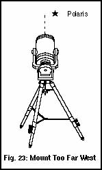 |
 |
a. If the star drifts South (or down), the telescope's polar axis is pointing too far East (Fig. 22).
b. If the star drifts North (or up), the telescope's polar axis is pointing too far West (Fig. 23).
4. Move the wedge in azimuth (horizontally) to effect the appropriate change in polar alignment. Reposition the telescope's East-West polar axis orientation until there is no further North-South drift by the star. Track the star for a period of time to be certain that its Declination drift has ceased. (Please note that Figs. 22, 23, 24, and 25 show the telescope pointed in the 90 degree position, and not the 0 degree position that is required for "Drift" method alignment. This is done to illustrate the position of the pole star relative to the polar axis of the telescope.)
5. Next, point the telescope at another moderately bright star near the Eastern horizon, but still near the celestial equator. For best results, the star should be about 20° or 30° above the Eastern horizon and within ± 5° of the celestial equator.
6. Again note the extent of the star's drift in Declination:
a. If the star drifts South, (or down) the telescope's polar axis is pointing too low (Fig. 24).
b. If the star drifts North, (or up) the telescope's polar axis is pointing too high (Fig. 25).
7. Use the latitude angle fine-adjust control on the wedge to effect the appropriate change in latitude angle, based on your observations above. Again, track the star for a period of time to be certain that Declination drift has ceased.
The above procedure results in very accurate polar alignment, and minimizes the need for tracking corrections during astrophotography.
APPENDIX C: LX200 ALIGNMENT STAR LIBRARY AND STAR CHARTS:
1. Alignment Stars
The LX200 utilizes 33 bright and well known stars to calibrate the telescope's Object Library in the ALTAZ and POLAR alignments. These stars were selected to allow observers from anywhere in the world on any given night, to be able to easily and quickly make precision alignments. The LX200 Alignment Star Library and Star Charts are below for your reference:
 |
| Star Chart 1 |
|---|
 |
| Star Chart 2 |
APPENDIX D: LX200 64,359-OBJECT LIBRARY
1. The LX200 64,359-Object Library
The LX200 64,359-Object Library is a collection of the most studied and fantastic objects in the sky.
This library consists of the following object databases:
- 15,928 SAO (Smithsonian Astrophysical Observatory) Catalog of Stars: All stars brighter than 7th magnitude.
- 12,921 UGC (Uppsala General Catalog) Galaxies: Complete catalog.
- 7,840 NGC (New General Catalog) objects*: Complete catalog.
- 5,386 IC (Index Catalog) objects*: Complete catalog.
- 21,815 GCVS (General Catalog of Variable Stars) Objects: Complete catalog.
- 351 alignment stars for the LX200 telescope.
- 110 Messier objects.
- 8 Major Planets.
You will notice that the Messier (M) objects, and the NGC objects have been incorporated into the Meade Instruments CNGC listing. CNGC stands for "Computerized New General Catalog of Non-Stellar Astronomical Objects". The CNGC is an enhancement from the RNGC (Revised New General Catalog) in many ways. Angular sizes are given in arc-seconds on the CNGC listing, and in a convenient scaled format on the LX200 Keypad Display.
The complete CNGC contains 7840 objects most of which appear in the RNGC (Revised New General Catalog) with the same number. More than 400 objects were added to the RNGC to create the CNGC. Most of these "should have been" in the RNGC in the sense that they are bright and large enough to have been included.
The CNGC is enhanced from the RNGC in many ways. Angular sizes are given in arc-seconds on the CNGC listing, and in a convenient scaled format on the LX200 display. Magnitudes are given to .1 magnitude where possible.
The coordinates in the CNGC listing are listed for the year 2000. The LX200 calculates object positions upon power up to the current date (as shown on the time/date display). This makes the LX200 pointing more accurate. Therefore, the CNGC listing and the LX200 display will not exactly agree on object positions.
Objects have been assigned a "Visual Quality Rating", henceforth called VQ. A large number of VQs have been obtained by observing the objects. To make the VQs as useful as possible, all observations have been made with the same telescope and eyepiece under substantially identical observing conditions. Only for very small objects was a higher power eyepiece used. Your "Visual Quality Rating" of a particular object will vary, largely due to sky conditions.
If the object has been rated by observation, an upper-case character (ABCDEFG) is used for the VQ on the CNGC listing. If the object has not been observed, the VQ has been estimated by a computer program from the object type, size, and brightness and the VQ is specified in lower-case characters (abcdefg). The VQs for visually-rated objects are a considerably more consistent guide to observability and appearance than either the computed VQs or an examination of the type, magnitude, and size data.
* NGC 2000 and IC databases are copyrighted by Sky Publishing Corporation and used with their permission.
The following guide to VQs was used in the visual observing process.
 |
| Table 9a: VQ Guide |
|---|
All, or very nearly all, of the objects in the CNGC are visible with the standard instrumentation and observing conditions used to obtain the visual quality ratings. It is a good indication of what can be expected with similar equipment by experienced deep-sky observers in excellent sky conditions. Naturally smaller telescopes and/or less optimal observing conditions will lower the apparent quality of all objects.
The following is a description of the format of the optional CNGC listing for each object:
 |
| Table 10: CNGC Listings |
|---|
The following types are distinguished in the CNGC.
 |
| Table 11: CNGC Types |
|---|
3. The Star Catalog
The STAR Catalog contains the 250 brightest stars (STAR 1 through STAR 250), 100 interesting double stars (STAR 251 through STAR 350), plus Sigma Octantis, the southern pole star (STAR 351).
4. Select Star by Name
When selecting a star from the object library, any of the 33 stars listed in the LX200 Instruction Manual can now by accessed by its name.
1. Press the STAR key. The Keypad display will show "STAR object:" on the first line and a blinking cursor on the second line.
2. To enter a Star by number, simply type in the star number and press ENTER, as described in the LX200 Instruction Manual.
To enter a Star by name, press the ENTER key. The Keypad display will show a new menu.
3. Select the NAME menu option by pressing the ENTER key.
4. Scroll through the list of Star names (using the PREV and NEXT keys) until the desired Star name is selected.
5. Press ENTER to select this Star.
5. The M Catalog
The M Catalog has been the benchmark deep-sky catalog for years. Recently expanded to 110 objects, the M (Messier) catalog contains most of the best deep-sky objects.
6. The Planets
The LX200 calculates the orbital positions of the eight major planets for the current calendar date. To access a planet, use the STAR key and enter the appropriate number as indicated below:
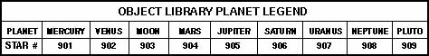 |
| Table 12: Object Library Planet Legend |
|---|
7. Other Databases
The other object catalogs are accessed through the CNGC key on the Keypad.
1. Press the CNGC key. The Keypad display will show "NGC object:" on the first line and a blinking cursor on the second line.
2. To enter a NGC object, simply type in the NGC number and press ENTER, as described in the LX200 Instruction Manual.
To enter an object from a different database, press the ENTER key. The Keypad display will show a new menu of the available databases.
3. Select the database from the menu by moving the arrow to the selection desired and pressing the ENTER key. Press MODE to exit the database menu.
4. The Keypad display will ask for the object number. Enter the object number desired and press ENTER.
The LX200 will "remember" the database you last accessed. Each time you press the CNGC key, the same object database will be displayed on the first line of the Keypad display. To change databases, press ENTER to bring up the database menu.
The STAR databases are accessed by pressing the STAR key and following the above steps.
Variable stars from the GCVS are entered using a six digit number. The first two digits, refer to the constellation where the variable star is located and is listed in the table below.
The next four digits are assigned sequentially within each constellation according to the standard sequence of variable-star designations (R, S, ...).
Therefore, the first variable star in the constellation of Virgo would be entered as: 860001.
 |
| Table 13: Constellation Codes |
|---|
Copyright © 1996 Meade Instruments Corporation, All Rights Reserved.