Telecentric assembly
(Copyright Christian Viladrich)
Telecentric systems for solar observation
Impact of tilt on telecentricity
(Edmund Optics schematic)
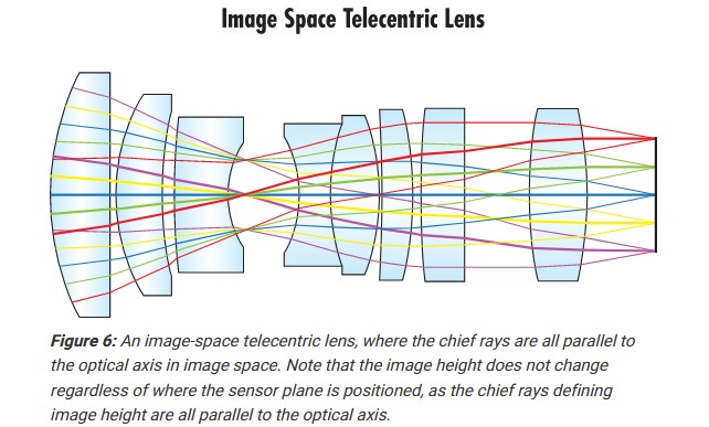
Use: Telecentric systems are used in narrow band observation (Ha) in order to achieve a constant CWL (Center Wave Length) and FWHM over the field of view (no sweet spot effect).
Note: in a telecentric system, defocus in the image plane (i.e. change of focus position) does not change image height or magnification. In other words, magnification factor of image-space telecentric systems does not change with the back focus.
Telecentric system for solar observation
A typical telecentric assembly for solar observation consists in a divergent group (B) followed by a convergent group (C).
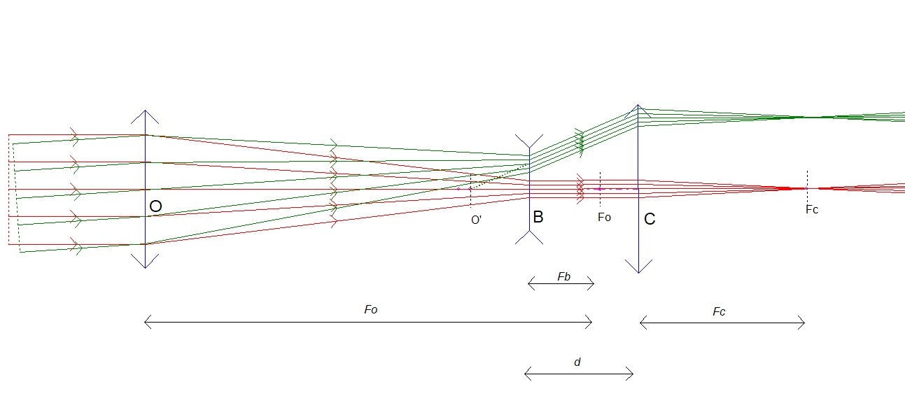
- The distance between C and the resulting focal plane Fc of the telescope is equal to the focal lens (Fc) of the converging group C.
- The distance d between B and C is set to that the chief rays (= axis of symetry of the light cones) are parallel to the telescope optical axis between (C) and the focal plane. To be so, the front focus of the convergent group C should coincide with the image O' of O given by group B.
The magnification factor M of the telecentric system is equal to Fc/ Fb
Because the angle of the chief rays is constant over the the surface of the filter (i.e. the chief rays are normal to the filter), there is no change in CWL of FWHM over the field of view (i.e. no sweet spot).
Important notes:
a) In the previous drawing, the "lens" O represents any type of telescope (including its Barlow lens if any). The focal length of the telescope is the only parameter that is involved in the telecentricity condition.
Strictly speaking, a telecentric assembly is telecentric only for a telescope of a given focal lens. Still, there are some flexibility in the focal length of the telescope as illustrated at the bottom of this page:
b) Appart for the telecentric condition, a
telecentric assembly has an impact on the optical aberrations present
in the final image (coma, spherical aberration, etc.). Accordinly, some
telecentric assembly might be optimized for a given telescope design
(e.g. AiryLab telecentric assembly are optimized for Celestron EdgeHD).
The role of each element of the telecentric system can be understood with the following simulations made with very nice software OpGeo http://jeanmarie.biansan.free.fr/optgeo.html
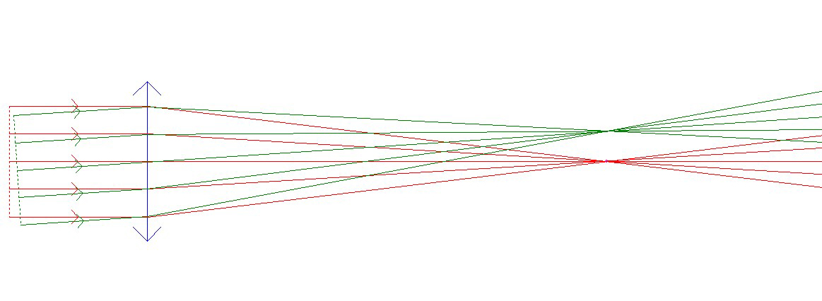
Stage 2: Let's add a divergent group placed at a position where both the focus of the divergent element and the telescope lens coincide:
Stage 3: Let's add a convergent lens. Here, it is placed too far away, resulting in convergent chief ray:
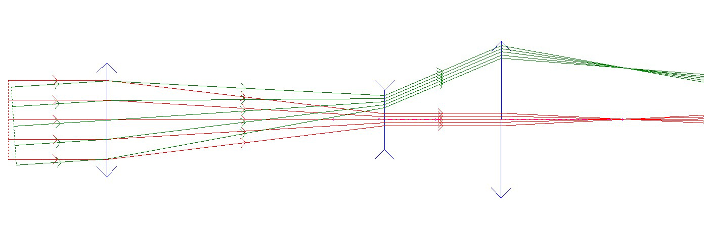
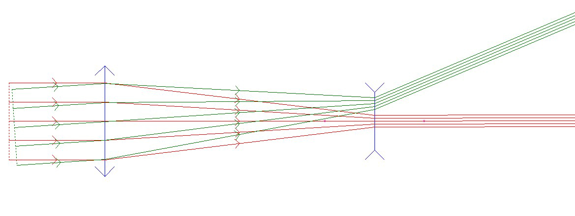
Stage 4: Let's move forward the convergent lens. Here, it is too close, resulting in divergent chief ray:
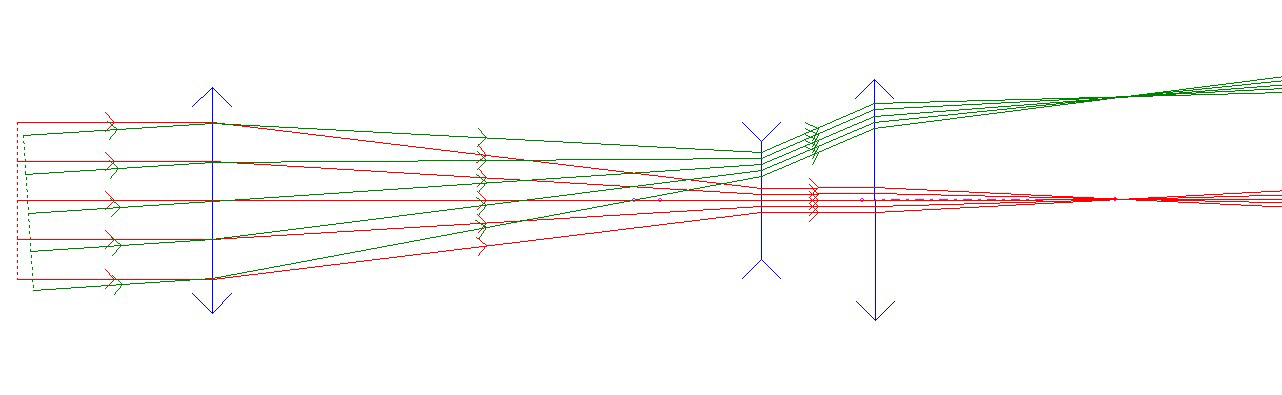
Stage 5: Now, the convergent lens is at the right position. The system is telecentric. The chief ray is parallel to the optical axis::