Stack
tests with a 1.5 A filter
1)
Center Wave Length (CWL)
and bandpass (FWHM) as a function of the F/D ratio of the telescope and
of the tilt of the F-P filter (collimated beam, telecentric beam,
non-optimized telecentric system)
2)
CWL shift and FWHM broadening in non telecentric lens systems
3)
Daystar filter modelling and additional results
4)
Air-spaced F-P etalon theoritical performances
5)
Analysis of the PST modification (air-spaced F-P etalon) and comparison
with mica-spaced F-P etalons
6)
Contrast factor of the F-P etalon and blocking filter assembly
7)
Contrast factor of the F-P etalon : test of various stacking schemes
8)
Fabry-Perot math and bibliography
Acquisition
/ processing :
Takahashi TOA150 +
TZ-4 + Basler 1920-155.
June 1, 2019.
Good seeing condition for all images : 0.4 to 0.5
arsec measured with the SSM.
Linear visualisation and same threshholds for all images.
No gamma at acquisition nor for processing.
Unsharp mask. No local processing.
Transmission
factor of the 1.5 A filter :
2.5 factor between with / without 1.5 A
stack measured with the SolarSpectrum RG 0.3A.
If both filters were perfect one-cavity
etalons, the
ratio between the 0.3A and the 0.3A + 1.5A would be x1.38 transmission
factor. Accordingly, the peak transmission of the 1.5 A
filter is
estimated to 1.38 /2.5 = 55%, which seems realistic.
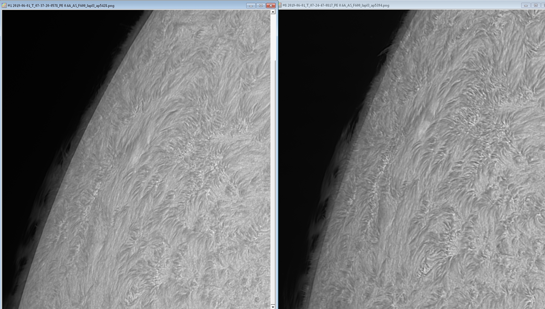
Daystar PE
0.6A (left) versus Daystar PE 0.6A + 1.5 A filter (right) :
The benefit of the stack with the 1.5 A
filter is obvious.
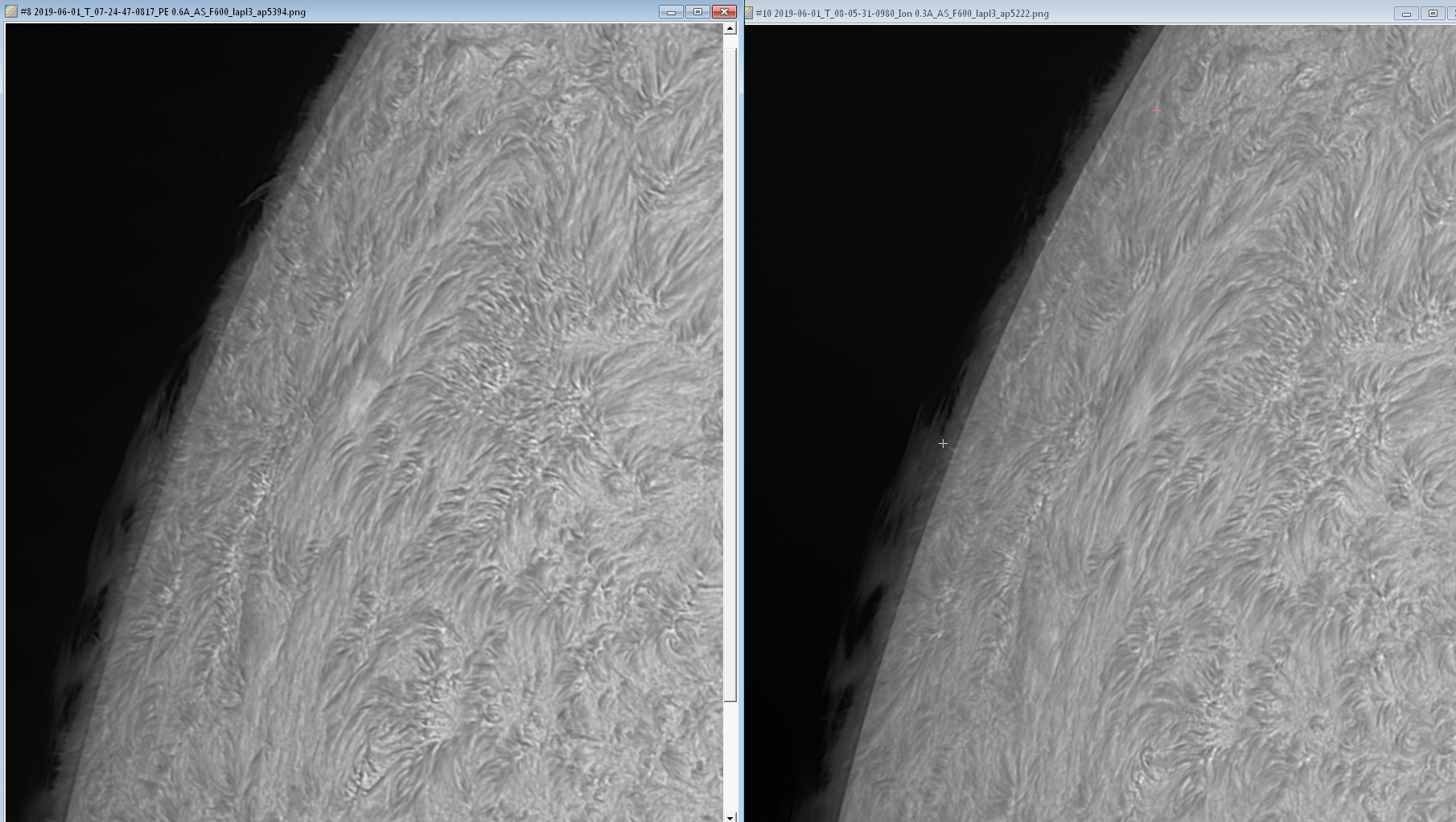
Daystar PE
0.6A + 1.5 A filter (left) versus
SolarSpectrum RG 0.3 A (right)
The 0.6 A + 1.5 A stack is clearly better
than the 0.3 A single stack.
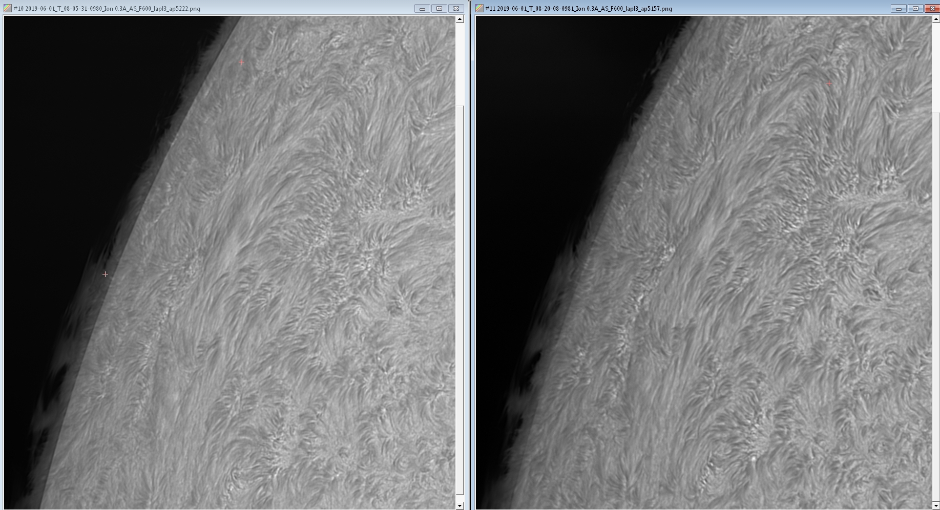
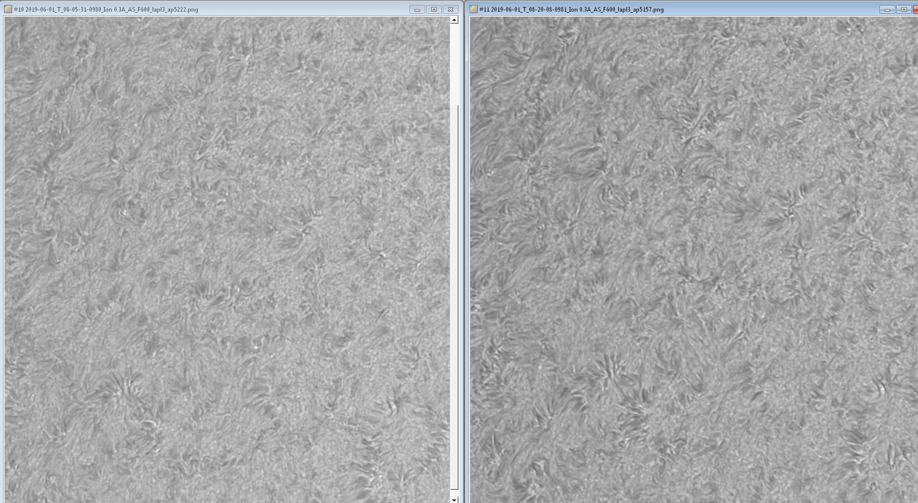
SolarSpectrum
RG 0.3 A (left) versus
SolarSpectrum RG 0.3 A + 1.5 A filter (right)
Once again,
the stack with the 1.5 A filter gives a big boast to the
contrast (i.e. better Ha line separation).
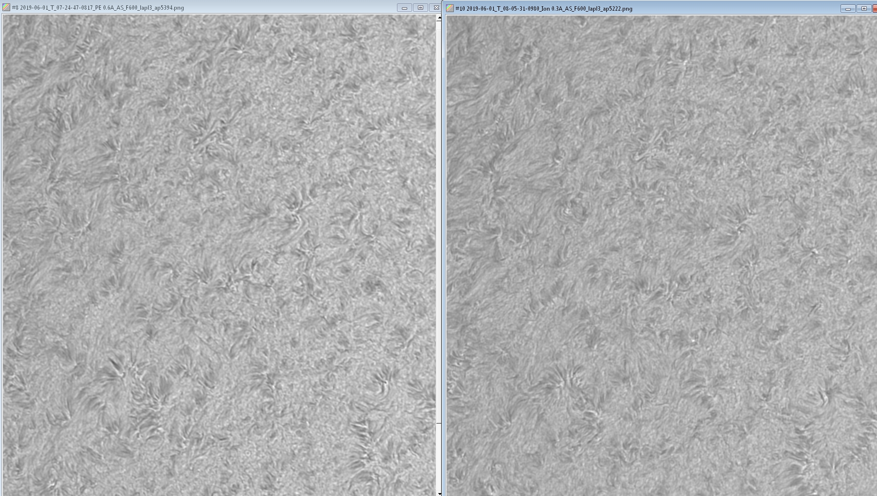
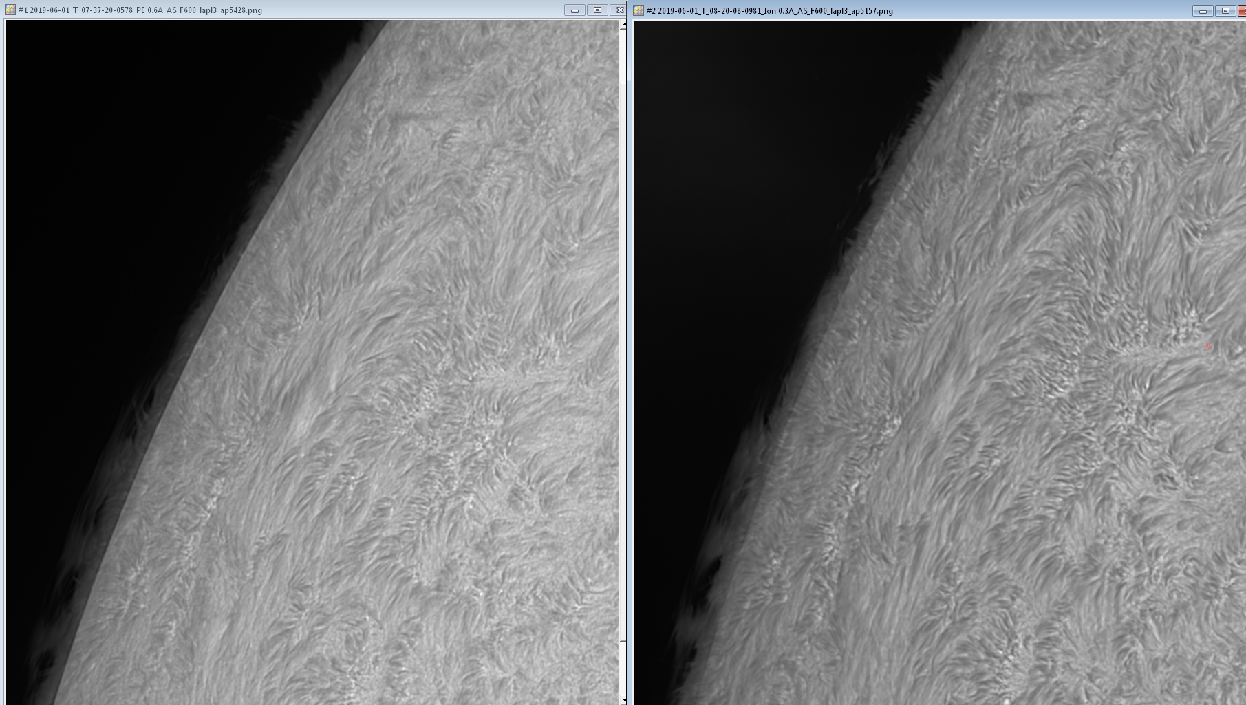
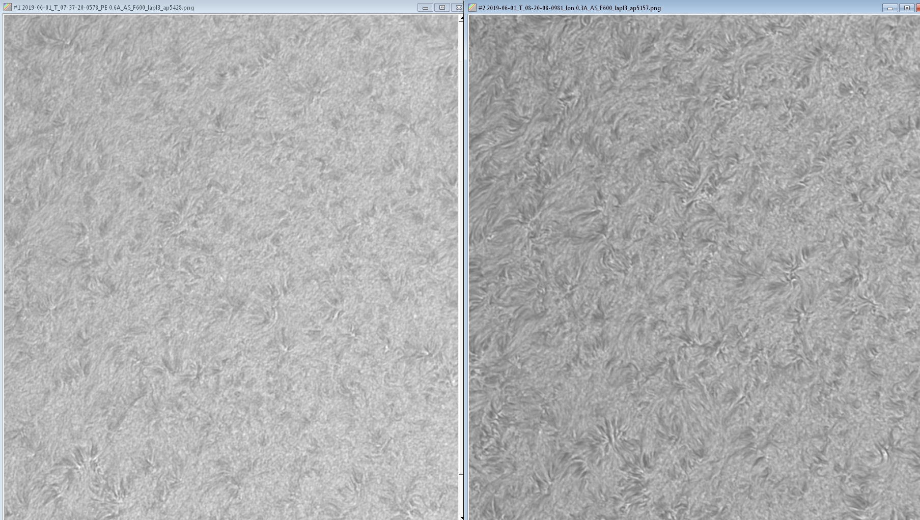
Daystar PE
0.6A + 1.5 A filter (left) versus
SolarSpectrum 0.3 A + 1.5 A
filter (right)
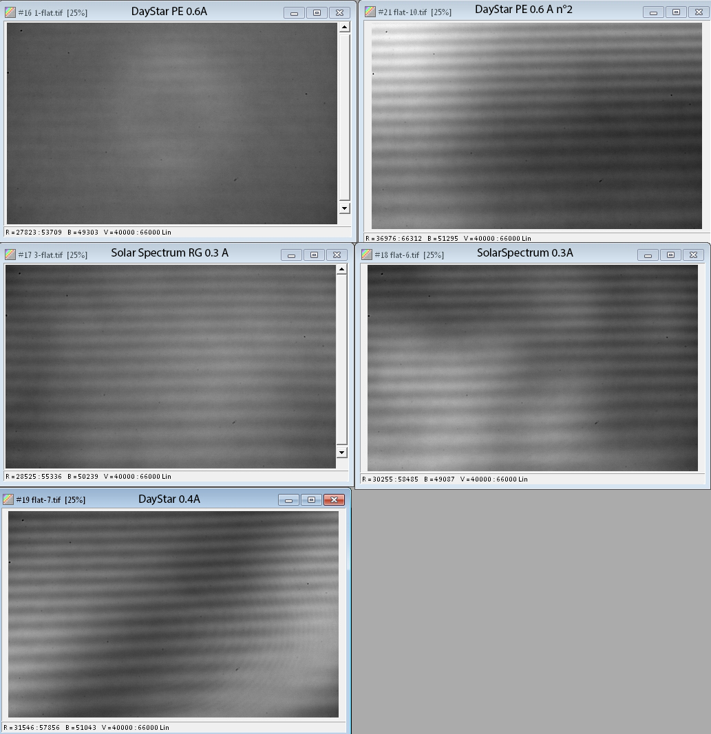
Flat comparison
All flats are normalized
to same average and displayed with same thresholds.
Files