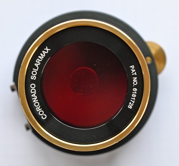
Coronado SM 40 #2
(January 2022)
| Test method | f-ratio | Surface sampled | FSR | FWHM | Delta CWL | Note | |
| Coronado SM40 etalon #2 |
Ha lamp |
collimated |
Full aperture |
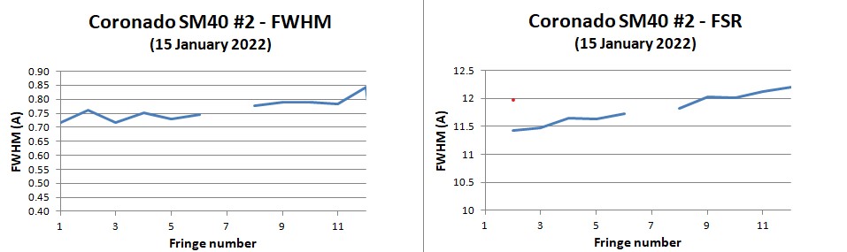
11.9 A |
0.95 A |
0.9 A |
variation of CWL from central spacer to outer rim of the etalon |
| Sol'Ex spectro | f-155 |
10 micron x 4.5 mm | 11.8 A | 0.76 A | |||
| BF 5 diagonal | Sol'Ex spectro | f-14.4 | 10 micron x 4.5 mm | Not relevant | 6.9 A | +1.5 A | 2-cavity filter |
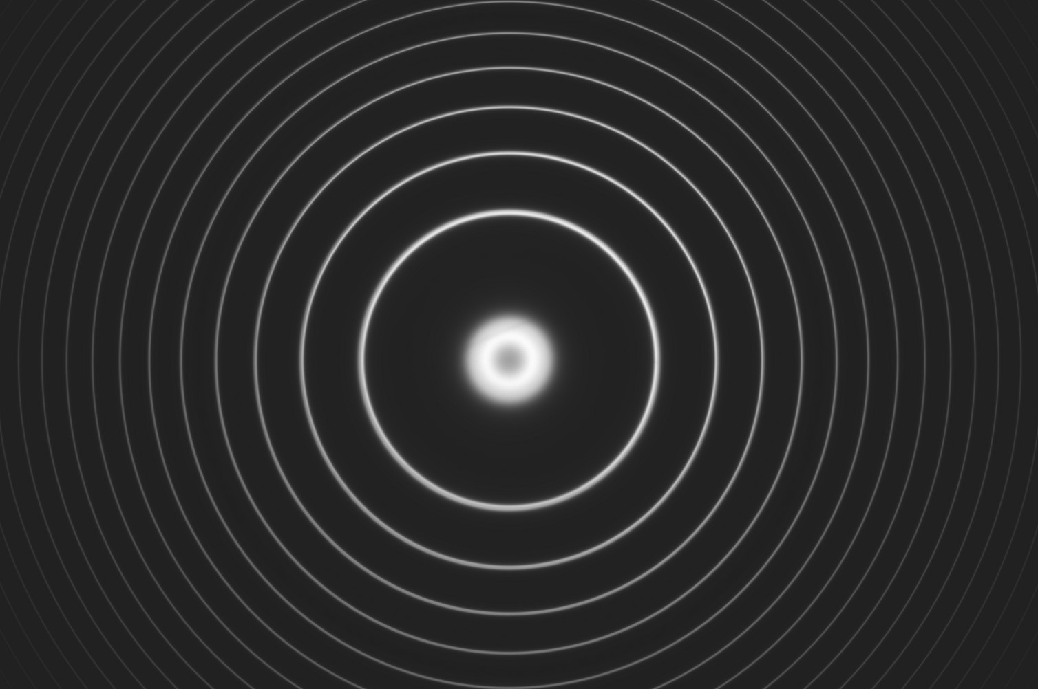
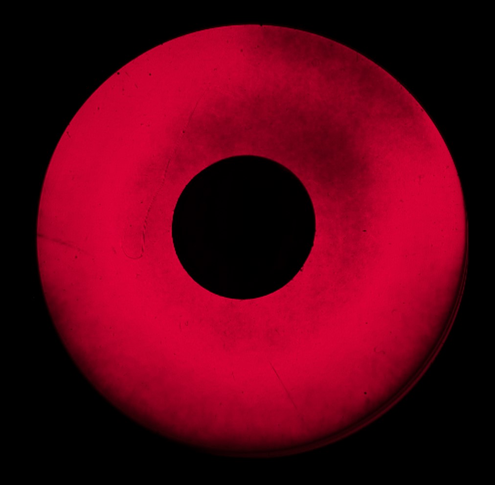
SM40 #2 - Interference fringe pattern - Nikon Z6 - 85 mm S f/1.8 Nikkor lens at f/2 (i.e. 42 mm aperture) - 12-bit RAW file - 1 s - 100 ISO - 10 January 2022
Some comments on this filter:

SM40 #2 - Reflected fringe pattern seen when the etalon is in the "reverse" position (RG630 side to the camera lens) - Nikon Z6 - 85 mm S f/1.8 Nikkor lens at f/1.8 (i.e. 42 mm aperture) - 12-bit RAW file - 1/2 s - 100 ISO - 18 January 2022
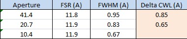
The filter was measured with lens f-ratio of f/2 (42 mm aperture), f/4 (21 mm aperture) and f/8 (10.5 mm aperture):
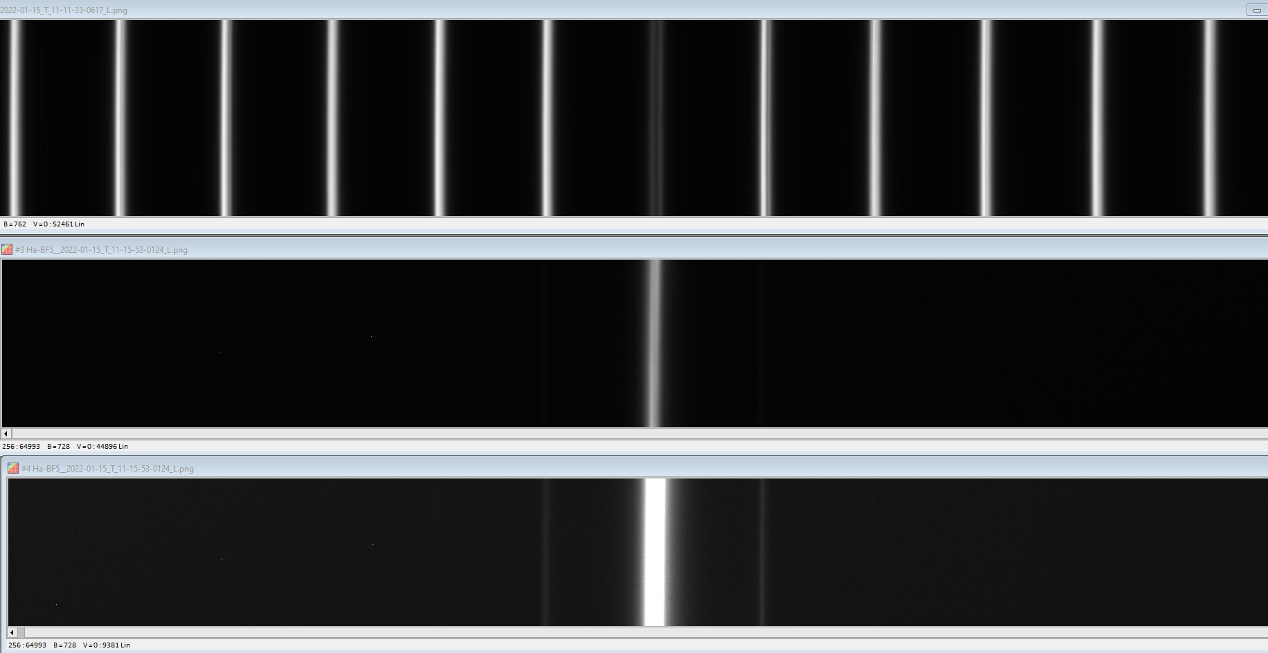
Test of the etalon with Sol'Ex spectrometer
Optical setup: Sun => Coronado SM 40 => Vixen 55 mm f/8 fluorite refractor => Coronado SM40 (with.without BF5) => Sol'Ex => ASI 290 (0.0753 A/pixel dispersion)
Three succesive images :
- SM40 alone,
- SM40 + BF 5 diagonal,
- SM40 + BF 5 diagonal, but with different visualisation threshold in order to make visible de secondary transmission.
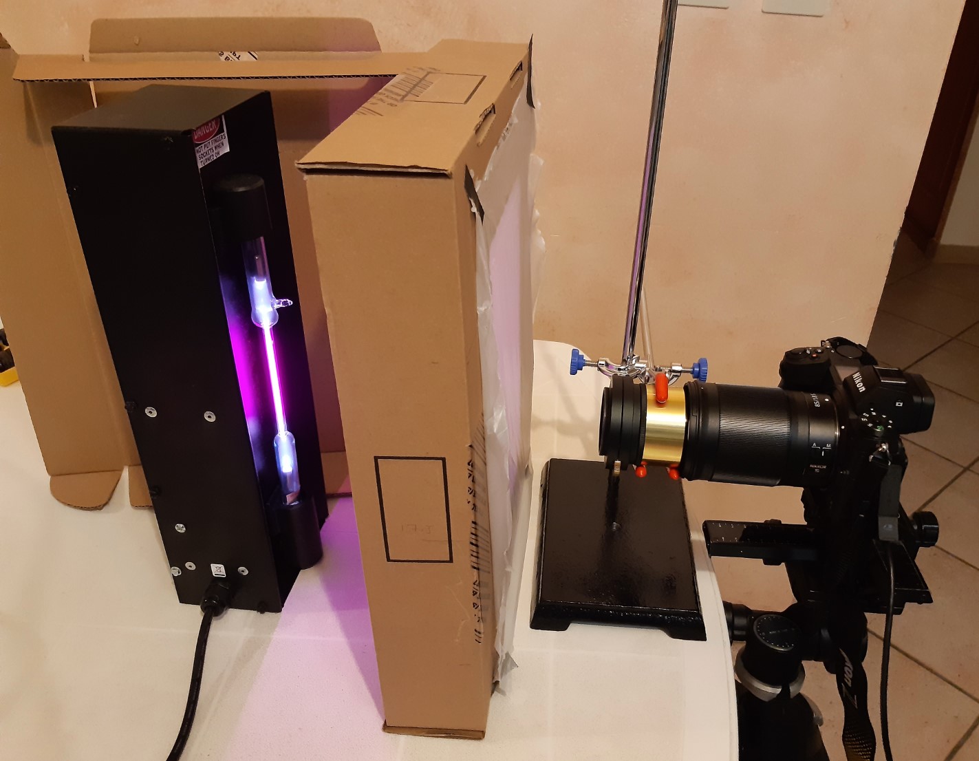
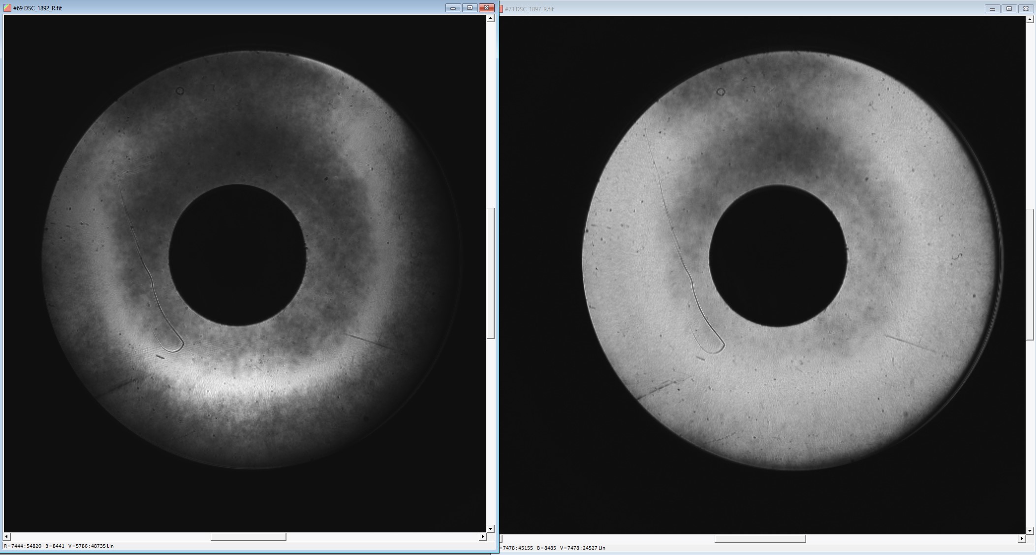
Test of the etalon in collimated Ha light
Optical setup: Ha lamp => Fluorite 55 f/8 used as a collimator => Coronado SM 40 => Nikon Z6 with 85 f/1.8 lens at full aperture
1/30 s - 100 IS - 14 bit acquisition - RGB - Linear vizualisation - 17 Jan 2022
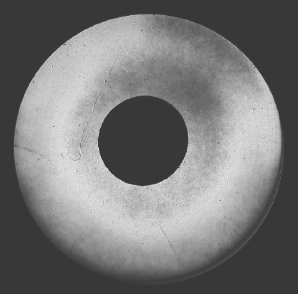
1/30 s - 100 ISO - 14 bit acquisition - Red channel - Linear vizualisation - 17 Jan 2022.
Interpretation of the image:
Non uniformities in Ha transmission appears as changes in brightness level. The bright areas correspond to areas where the transmission of the etalon in Ha is the highest.
If the etalon was completely uniform, the brightness level would be the same over all the surface of the etalon.
Small scale linear defaults (scratches, inclusions, etc.) can also be seen as well and small scale polishing default (circular pattern) and surface roughness. These defaults have no impact on the image quality.
Scanning the etalon CWL
In the following set of images, the etalon is tilted progressively from left to right.
- Tilting the etalon moves its Central Wavelength (CWL) to the blue.
- For each tilt position, the area whose CWL is on Ha is the brightest. So tilting the filter is a way to scan the CWL over the aperture of the etalon.
- The bright areas in the image with no tilt are the areas which are on Ha at normal incidence (no CWL offset).
- The areas which require more tilt to become bright are the area farther from Ha (their CWL is offset from Ha to the red side of the spectrum).
- The central image is the most balanced. This is the one closest to the optimal tilt (most of the etalon aperture CWL is on Ha). The tilt is 0.9°, equivalent to a delta CWL of 0.8 A, which is close to the more accurate value found in the test in diffuse light.
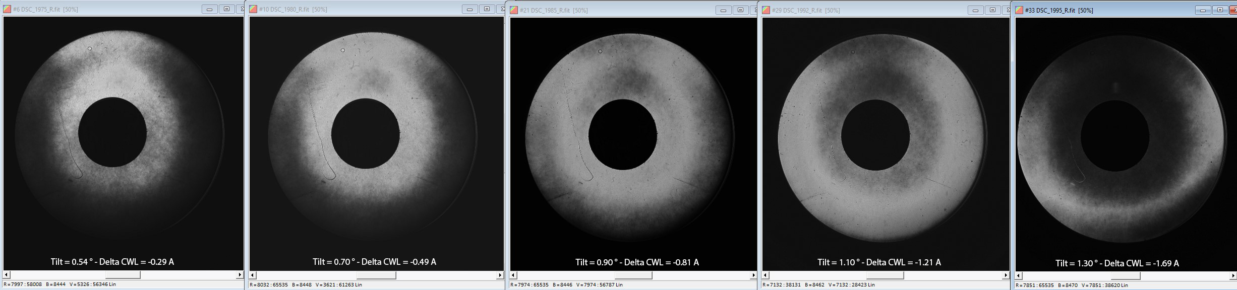
Etalon tilted with increasing angle from left to right. 14 bit acquisition - Red channel - Linear vizualisation - 23 Jan 2022
Test of Coronado BF 5 diagonal with Sol'Ex spectrometer
Test n°1 (12 Jan 2022)
Optical
setup: Collimated Led source => Takahashi 106 FSQ => 1.8x
Barlow lens => Coronado BF5 diagonal => Sol'Ex => ASI 290
(0.0753 A/pixel dispersion)
20.5 C temperature.

Results
FHWM = 6.9 A
Bandwith at 10% peak transmission = 11.8 A
2-cavity filter
Test n°2 (13 Jan 2022)
Transmission is calculated as the ratio between the spectrum transmitted by the BF5 and the solar spectrum maesured without the BF5.
NB:
- The dent at 6562.8 is an artefact.
- The incident light beam falls onto the BF5 at f/14.4. When measured at f/8, the FWHM enlarges slightly to 7.2 A.
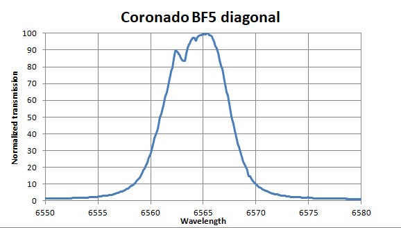
Results
FHWM = 6.9 A
Bandwith at 10% peak transmission = 11.5 A
CWL offset : +1.5 A
2-cavity filter