This cell and with its support system has been developed over many years and are the result of work from many people. As I've mentioned on the web page, I haven't created anything of my own but the great performance of this cell has convinced me to try it on my own scope, a 22-inch Dobsonian on an equatorial platform. Astatic means always in balance. This cell is interesting for use with large thin mirrors. Not long ago, the design used levers that were necessary for each point, needless to this "forest" of levers under the cell made it really hard to "tune" the cell for optimal performance. This hybrid astatic cell is a combination of triangles like that, which is used in a conventional flotation cell. The astatic cell has existed for quite a long time but that "forest of levers" was really complicated. With this hybrid, it's no longer true. The usual design for a mirror cell used in a large DOB is the classical flotation system. This cell is a system of balanced "layers" of triangles and a joining bar. When the 'scope moves up and down, these triangles and joining bars also need to move to maintain their balance. When these "layers" move, there is friction between them. Everywhere there is a contact point with movement; it's a potential friction. This friction is never the same and it can give a random position of the points and cause a distortion to the optic surface. These different positions give an "always changing" support of the mirror. This changing force produces tension. One can see how a large mirror blank can act like rubber and if the glass is thin enough, it is noted that the cell can easily deform the glass. The weight of a large mirror puts enough force to cause enough friction in the cell flotation system. If the number of supports increases, this can give even more problems. In order to properly support larger and thinner mirrors, some people have made a 54-point mirror cell or even more. That means even more chances for the friction to cause problems. When the OTA is moved down, the triangles are "unloaded" and the sling carries the weight of the mirror. When the 'scope is move up, the weight goes back to this "random" cell without any control. With astatic levers, it's different. There is only one layer of triangles, like for an ordinary 9-point cell. With fewer layers in the system it means less effect from friction. Also, triangles are of course not free of friction but they are very much reduced. The levers axis of rotation is achieved using a female cone and a matching conical point, so the possible frictional surface area is very small. Using a "chrysocal" blade (called flexural pivots), it's even less cause for friction, it's an "elastic" lever made with a metal that always comes back to the same position. For the transmission of the push of the counterweight, it is the same thing. Some astatic cells use a transmission part (a "piston") that can give some friction but it's possible to use a chrysocal blade or other metal to transmit the effort with very minimal problems, so the push that was given to levers sometime to release tension is very reduced, a simple movement at the begining of the night is enough. Astatic levers only transmit a pressure, a strength, not a movement. Parts don't move. It's not a question of moving parts but a question of effort applied with little friction in order not to hinder motion. The triangles always apply the same force to the glass. When the 'scope is moved down, the counterweight regularly gives less and less push and lets the lateral support carry the weight. When the scope is point up, the counterweight has more and more "power" to carry the load, always the same way because the position is still the same. This difference, compared to a classical cell is that it is totally reproducible and always gives the same thing. On the cell, there are 3 "fixed" points (or 3 triangle on sphere to allow movement for a 18 points cell) that are evenly located around the triangle. They maintain the mirror on is position in "space" and can't move vertically or horizontally. The other triangles with levers simply apply a force that is proportional to the amount of glass they have to carry. Their is no "piston" movement that raises the mirror from it's position on the 3 fixed points. Lateral support made with piano wire works in compression. It's also a transmission of an effort. When the blank is carried more and more by the lateral support, they are always in close contact with the Teflon tipped pads on top of that support. The piano wires slowly carry the load and received the effort. As it is a highly elastic material used longitudinally, it resist to the pressure laterally while still allowing the mirror to "float" on the levers. With 3 of these supports around the circumference, and the astatic levers of the cell, there is no longer a lateral movement problem of the mirror if used on an equatorial platform for example. No foam or anything else. The cell keeps the glass accurately in only one position. There is no movement; it's simply a question of transmission of weight without friction. This cell and lateral supports are not very hard to make. I have made mine with the same tools need to make a standard flotation cell. If a lathe is available it's of course easier to make some parts but it's possible to make them with a saw and a drill press. The price of the different elements is about the same than for a classical cell too. Counterweights can be made using a heavy metal that doesn't cost a fortune (lead comes to mind). The added weight of the counterweights can slightly increase the weight of the total scope, for about 1/5 of the weight of the glass. Due to some poor OTA layout, it is often necessary to add some counterweight at the bottom of the OTA. I prefer see it as something useful than simply dead weight. It's probably possible to reduce the weight of counterweights but this ratio works quite well. Experimenting is of course possible. I have used this cell and have really been pleased with it. I must confess that the first time I saw one; it was really a strange feeling, what a complicated thing. It looks complicated but really, it's not. Thanks to software like PLOP, calculating the points is no longer hard to do. Of course, a classical cell could have some enhancements, like a special effort to reduce the friction of the flotation triangles, the astatic cell doesn't require complicated tools to make and I prefer to choose this much forgiving system. The Lateral Supports are also quite strange but now really love them. They enable an accurate positioning of the mirror in the OTA. Like the saying, "Holding a mirror is like holding your girlfriend, hold her close and secure but NO PINCHING"! When pointed at a very low position they can give astigmatism, but as it is not the way large scopes are used, that's not a big problem. The collimation is much better kept over the course of few nights and the glass is in perfect shape, no matter where the 'scope is moved. All that may look strange but I will not make a large Dob using a conventional cell again because it's easier not to bother with mirror distortions caused by binding flotation triangles or improperly positioned slings when those rare moments of good seeing occur. It's of course some more works but use a large thin mirror as it full potential worth the effort. | |||||||||||||||||||||||||||||||||||||||||||||||||||||||||||||||||||||||||||||||||||||||||||||||||||||||||||||||||||||||||||||||||||||||||||||||||||||||||||||||||||||||||||||||||||||||||||||||||||||||||||||||||||||||||||||||||||||||||||||||||||||||||||||||||||||||||||||||||||||||||||||||||||||||||||||||||||||||||||||||||||||||||||||||||||||||||||||||||||||||||||||||||||||||||||||||||||||||||
When one wishes to have the best possible images with the eyepiece, the first condition to fill is to have good mirrors. But this good mirror has a large handicap if it’s not supported in a high quality mirror cell. Indeed, it's useless to have exceptional optics of l/16 wave or better if you let it become deformed on an unsuited support. When one starts to think about making a large instrument, it's hard to believe that such a mass of glass is so very flexible. Alas, it is true. The most widespread form of support in the world of Dobsonians is the usual arrangement of floating triangles combined with the sling. This system has the advantage of being simple to fabricate because the parts are basic enough to be easily made with simple tools. However, this type of support has a certain number of traps that can all contribute to deform the primary mirror’s shape. In order to preserve a good mirror the sling should be replaced by a support like that described in the page " Improvement of the side support of a mirror ". These supports also allow keeping the optical axis because there is no more the " elastic " phenomenon of the sling.
| |||||||||||||||||||||||||||||||||||||||||||||||||||||||||||||||||||||||||||||||||||||||||||||||||||||||||||||||||||||||||||||||||||||||||||||||||||||||||||||||||||||||||||||||||||||||||||||||||||||||||||||||||||||||||||||||||||||||||||||||||||||||||||||||||||||||||||||||||||||||||||||||||||||||||||||||||||||||||||||||||||||||||||||||||||||||||||||||||||||||||||||||||||||||||||||||||||||||||
| |||||||||||||||||||||||||||||||||||||||||||||||||||||||||||||||||||||||||||||||||||||||||||||||||||||||||||||||||||||||||||||||||||||||||||||||||||||||||||||||||||||||||||||||||||||||||||||||||||||||||||||||||||||||||||||||||||||||||||||||||||||||||||||||||||||||||||||||||||||||||||||||||||||||||||||||||||||||||||||||||||||||||||||||||||||||||||||||||||||||||||||||||||||||||||||||||||||||||
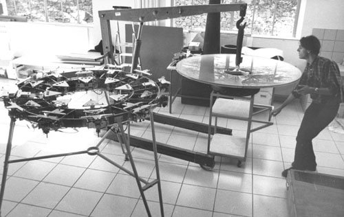
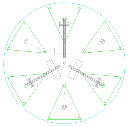
The multiple arrangements of triangles are another source of problems. They can generate deformations after each and every movement of the instrument because they sometimes don't go back to exactly the same position. These tiny differences seem unimportant at first but they apply unequal forces to the mirror. This phenomenon is called hysteresis (stress). These deformations can generate astigmatism, for example. Professional’s have made use now for many years using a mirror cell known as "astatic " which avoids these problems. Jean Texereau described this mirror cell principle for a Cassegrain of 250 mm (10") in " How to make a telescope". However this system becomes complicated when designed for significantly large diameter mirrors because a lever supports each point. The number of levers increasing, the realization is heavy and the adjustments become much more complicated. A significant evolution: In order to avoid the problem of complexity, the members of project OVLA have created a hybrid system with astatic levers and triangles. They pushed the concept very far as one can see it on the following image.
| |||||||||||||||||||||||||||||||||||||||||||||||||||||||||||||||||||||||||||||||||||||||||||||||||||||||||||||||||||||||||||||||||||||||||||||||||||||||||||||||||||||||||||||||||||||||||||||||||||||||||||||||||||||||||||||||||||||||||||||||||||||||||||||||||||||||||||||||||||||||||||||||||||||||||||||||||||||||||||||||||||||||||||||||||||||||||||||||||||||||||||||||||||||||||||||||||||||||||
| |||||||||||||||||||||||||||||||||||||||||||||||||||||||||||||||||||||||||||||||||||||||||||||||||||||||||||||||||||||||||||||||||||||||||||||||||||||||||||||||||||||||||||||||||||||||||||||||||||||||||||||||||||||||||||||||||||||||||||||||||||||||||||||||||||||||||||||||||||||||||||||||||||||||||||||||||||||||||||||||||||||||||||||||||||||||||||||||||||||||||||||||||||||||||||||||||||||||||
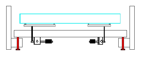
The levers no longer push only one point but a triangle supporting 3 points. This decreased the number of levers needed and the realization is largely simplified because there is less mechanics involved locating the place necessary for so many levers, which was sometimes problematic. It is an important progress that also benefits the adjustments to support the rear of the mirror, which now becomes simpler to realize. The realization of an astatic mirror cell is more complex than the traditional system. But an amateur with a minimum of equipment may find an important benefit here. Machining can be done in a shop with a lathe or in a simpler workshop using only a press drill. Operation: The way an astatic mirror cell functions is relatively simple, the counterweights placed on the levers under the bottom of the mirror cell, counterbalance the effect of gravity by applying a " push " to the back of the mirror proportional to its mass. When the optical tube is lowered towards the horizon, the weights apply a proportional force and the weight of the primary is thus gradually transmitted to the lateral supports. The mirror is not deformed because it undergoes a constant effort. It's progressive because the levers "move" (in fact they don't move, they simply transmit an effort, a strength or force) gradually by transmitting that force proportionally to the back of the mirror in response to the altitude of the scope.
| |||||||||||||||||||||||||||||||||||||||||||||||||||||||||||||||||||||||||||||||||||||||||||||||||||||||||||||||||||||||||||||||||||||||||||||||||||||||||||||||||||||||||||||||||||||||||||||||||||||||||||||||||||||||||||||||||||||||||||||||||||||||||||||||||||||||||||||||||||||||||||||||||||||||||||||||||||||||||||||||||||||||||||||||||||||||||||||||||||||||||||||||||||||||||||||||||||||||||
| |||||||||||||||||||||||||||||||||||||||||||||||||||||||||||||||||||||||||||||||||||||||||||||||||||||||||||||||||||||||||||||||||||||||||||||||||||||||||||||||||||||||||||||||||||||||||||||||||||||||||||||||||||||||||||||||||||||||||||||||||||||||||||||||||||||||||||||||||||||||||||||||||||||||||||||||||||||||||||||||||||||||||||||||||||||||||||||||||||||||||||||||||||||||||||||||||||||||||
The first important point is that this "effort" must be transmitted without any losses and that means no friction of the moving parts and the second important point is that the axis of this "effort" must be preserve.
| |||||||||||||||||||||||||||||||||||||||||||||||||||||||||||||||||||||||||||||||||||||||||||||||||||||||||||||||||||||||||||||||||||||||||||||||||||||||||||||||||||||||||||||||||||||||||||||||||||||||||||||||||||||||||||||||||||||||||||||||||||||||||||||||||||||||||||||||||||||||||||||||||||||||||||||||||||||||||||||||||||||||||||||||||||||||||||||||||||||||||||||||||||||||||||||||||||||||||
| |||||||||||||||||||||||||||||||||||||||||||||||||||||||||||||||||||||||||||||||||||||||||||||||||||||||||||||||||||||||||||||||||||||||||||||||||||||||||||||||||||||||||||||||||||||||||||||||||||||||||||||||||||||||||||||||||||||||||||||||||||||||||||||||||||||||||||||||||||||||||||||||||||||||||||||||||||||||||||||||||||||||||||||||||||||||||||||||||||||||||||||||||||||||||||||||||||||||||
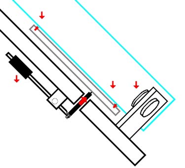
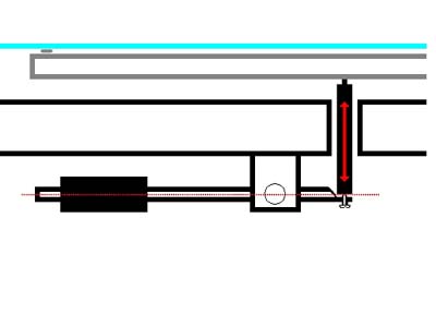
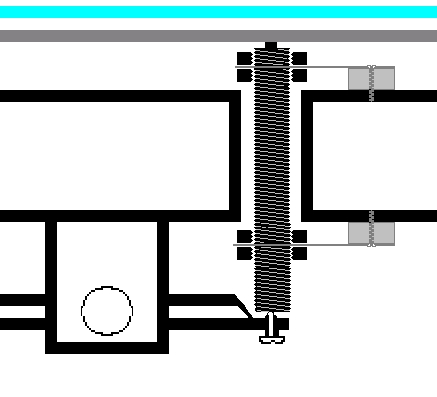
This axis is preserved thanks to the use of an adjustable screw located at one end of the lever. Two types of astatic mirror cells: There are two different ways to build the mirror cell. The collimation can be either adjusted by pushing directly on some of the points in contact with the back of the mirror as in the traditional method
| |||||||||||||||||||||||||||||||||||||||||||||||||||||||||||||||||||||||||||||||||||||||||||||||||||||||||||||||||||||||||||||||||||||||||||||||||||||||||||||||||||||||||||||||||||||||||||||||||||||||||||||||||||||||||||||||||||||||||||||||||||||||||||||||||||||||||||||||||||||||||||||||||||||||||||||||||||||||||||||||||||||||||||||||||||||||||||||||||||||||||||||||||||||||||||||||||||||||||
| |||||||||||||||||||||||||||||||||||||||||||||||||||||||||||||||||||||||||||||||||||||||||||||||||||||||||||||||||||||||||||||||||||||||||||||||||||||||||||||||||||||||||||||||||||||||||||||||||||||||||||||||||||||||||||||||||||||||||||||||||||||||||||||||||||||||||||||||||||||||||||||||||||||||||||||||||||||||||||||||||||||||||||||||||||||||||||||||||||||||||||||||||||||||||||||||||||||||||
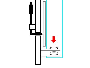
or the whole mirror cell can be made to give this adjustment.
| |||||||||||||||||||||||||||||||||||||||||||||||||||||||||||||||||||||||||||||||||||||||||||||||||||||||||||||||||||||||||||||||||||||||||||||||||||||||||||||||||||||||||||||||||||||||||||||||||||||||||||||||||||||||||||||||||||||||||||||||||||||||||||||||||||||||||||||||||||||||||||||||||||||||||||||||||||||||||||||||||||||||||||||||||||||||||||||||||||||||||||||||||||||||||||||||||||||||||
| |||||||||||||||||||||||||||||||||||||||||||||||||||||||||||||||||||||||||||||||||||||||||||||||||||||||||||||||||||||||||||||||||||||||||||||||||||||||||||||||||||||||||||||||||||||||||||||||||||||||||||||||||||||||||||||||||||||||||||||||||||||||||||||||||||||||||||||||||||||||||||||||||||||||||||||||||||||||||||||||||||||||||||||||||||||||||||||||||||||||||||||||||||||||||||||||||||||||||
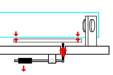
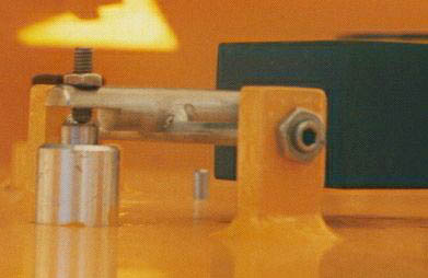
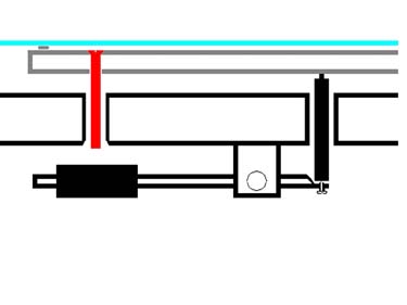
Transmission of the effort: The part, which receives the push of the astatic lever, must be free of friction. It is possible to use " pistons " machined with a high degree of accuracy. These pistons must be of a relatively small diameter (5 mm for one 500 mm for example), the smaller the diameter the less friction there is because of less contact between the surfaces. One should not fall into opposite excess by using too small a part to transmit the effort. To remove friction at much as possible, one can use a small sheet metal " (see page on the Chrysocal Levers). In this case, it is necessary to use a mirror cell on two levels because the clearance enabled by the chrysocal blade is not enough to allow collimation. A system with a piston has a clearance of several millimeters, so the collimation does not give any problem. The blades can also be made out of strip of steel. The blades are used to maintain the axis (here, a threaded rod). They are fixed on the bottom of mirror cell but their flexibility makes it possible to transmit the force. To avoid the rotation of the blades, it's better to attach them at the mirror cell with two screws.
| |||||||||||||||||||||||||||||||||||||||||||||||||||||||||||||||||||||||||||||||||||||||||||||||||||||||||||||||||||||||||||||||||||||||||||||||||||||||||||||||||||||||||||||||||||||||||||||||||||||||||||||||||||||||||||||||||||||||||||||||||||||||||||||||||||||||||||||||||||||||||||||||||||||||||||||||||||||||||||||||||||||||||||||||||||||||||||||||||||||||||||||||||||||||||||||||||||||||||
| |||||||||||||||||||||||||||||||||||||||||||||||||||||||||||||||||||||||||||||||||||||||||||||||||||||||||||||||||||||||||||||||||||||||||||||||||||||||||||||||||||||||||||||||||||||||||||||||||||||||||||||||||||||||||||||||||||||||||||||||||||||||||||||||||||||||||||||||||||||||||||||||||||||||||||||||||||||||||||||||||||||||||||||||||||||||||||||||||||||||||||||||||||||||||||||||||||||||||
Point of the support: The points of the mirror cell are very important and must be calculated with a great accuracy. The following numbers come from the Hansi program of Luc Arnold. They are optimized for these specific mirror dimensions. If your mirror is in this list, it is safe to use them. (measures in meter)
The design of the mirror cell depends of the number of support points used. A 9-point, a 12-point or an 18-point arrangement is not drawn in the same way. According to the choice selected, collimation will be carried on a triangle, or a fixed point. For diameters going from 400 to 609 mm calculations were carried out under the software PLOP V2.0 de David Lewis, Toshimi Taki and Tom Boutell. This wonderful software is relatively easy to use if one wishes to calculate the points of a traditional mirror cell. It can be downloaded with the following address: http://www.eecg.toronto.edu/~lewis/plop/ The figures are: diameter, thickness, F/D, distance compared to center first circle of points, distance from the second circle of points, then the center of gravity of the triangle when the mirror rests on its support. This last parameter is the place of the pushing level (piston or fixed point). (all measures in millimeters)
| |||||||||||||||||||||||||||||||||||||||||||||||||||||||||||||||||||||||||||||||||||||||||||||||||||||||||||||||||||||||||||||||||||||||||||||||||||||||||||||||||||||||||||||||||||||||||||||||||||||||||||||||||||||||||||||||||||||||||||||||||||||||||||||||||||||||||||||||||||||||||||||||||||||||||||||||||||||||||||||||||||||||||||||||||||||||||||||||||||||||||||||||||||||||||||||||||||||||||
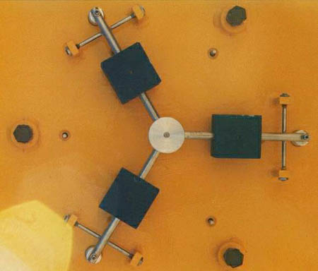
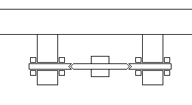
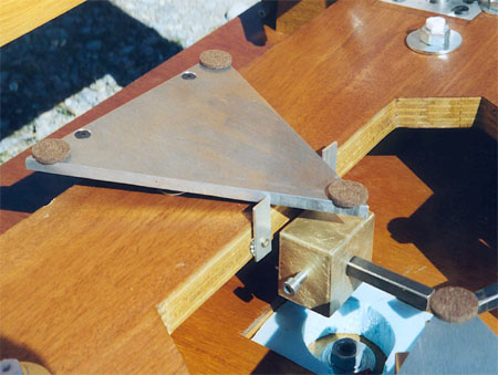
The points of contact should not be crushed or become deformed. These points must not adhere to the mirror back because they can also become a significant source of stress. It is possible to use Teflon pads of about 5 or 10 mm’s diameter and of around 3 mm thickness or the pads use under furniture. The problem is that they are nearly impossible to glue. The point of the "fixed" triangle (without level) or single point, must be strong and hard Triangles: The triangles must be balanced because their true center of gravity is not always the same with or without the weight of the mirror on them. A triangle must remain set and held in place with respect to the horizontal in the mirror cell with and without the mirror in place or it will apply its force to the back of the mirror in an un-desired pressure. It is possible to add a small mass allowing a rebalancing of triangle. The thickness of the triangles should not be made too thin because it is necessary to avoid any flexure. Aluminum or stainless is appropriate and very well if they are thick enough. The triangles have, at their points of support, a kneecap. This kneecap must have a soft and regular movement. In order to avoid the rotation of this triangle, it is necessary to place a metal axis that will block any possibility of exaggerated rotation. This axis must be interdependent of the triangle and pass through mirror cell but without being to tight. It must enable the triangle to move for few degrees
| |||||||||||||||||||||||||||||||||||||||||||||||||||||||||||||||||||||||||||||||||||||||||||||||||||||||||||||||||||||||||||||||||||||||||||||||||||||||||||||||||||||||||||||||||||||||||||||||||||||||||||||||||||||||||||||||||||||||||||||||||||||||||||||||||||||||||||||||||||||||||||||||||||||||||||||||||||||||||||||||||||||||||||||||||||||||||||||||||||||||||||||||||||||||||||||||||||||||||
| |||||||||||||||||||||||||||||||||||||||||||||||||||||||||||||||||||||||||||||||||||||||||||||||||||||||||||||||||||||||||||||||||||||||||||||||||||||||||||||||||||||||||||||||||||||||||||||||||||||||||||||||||||||||||||||||||||||||||||||||||||||||||||||||||||||||||||||||||||||||||||||||||||||||||||||||||||||||||||||||||||||||||||||||||||||||||||||||||||||||||||||||||||||||||||||||||||||||||
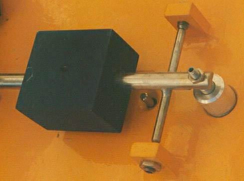
Levers: The axis of rotation of the lever is also a point not to be neglected. Indeed, it's important to reduce the friction as much as possible. A simple solution consists of using stainless cones and surface dug out of bronze. Other materials can be appropriate but those metals are excellent for this use because of the low friction using bronze. Avoid using “oil impregnated” bronze, as petroleum products tend to “creep” and will collect dust and hinder motion. A rod is machined to have a 60° cone shape at its two ends. In its middle is welded or screwed with the axis of the lever (that on which the weight is fixed). Cones carry these points and they are screwed on their support. The surface of contact is minimal so the friction is minimum too. The counterweight is placed on the rod and must be set (let of course a margin for the adjustment) in place in order to transmit soft movements, i.e. to maximize the lever effect, it is to better use one weak weight placed far from the center of rotation of the lever rather than a high weight placed close of the axis of rotation. One of the constraints will be, of course, the room available under the mirror cell to be able to put all these masses.
| |||||||||||||||||||||||||||||||||||||||||||||||||||||||||||||||||||||||||||||||||||||||||||||||||||||||||||||||||||||||||||||||||||||||||||||||||||||||||||||||||||||||||||||||||||||||||||||||||||||||||||||||||||||||||||||||||||||||||||||||||||||||||||||||||||||||||||||||||||||||||||||||||||||||||||||||||||||||||||||||||||||||||||||||||||||||||||||||||||||||||||||||||||||||||||||||||||||||||
| |||||||||||||||||||||||||||||||||||||||||||||||||||||||||||||||||||||||||||||||||||||||||||||||||||||||||||||||||||||||||||||||||||||||||||||||||||||||||||||||||||||||||||||||||||||||||||||||||||||||||||||||||||||||||||||||||||||||||||||||||||||||||||||||||||||||||||||||||||||||||||||||||||||||||||||||||||||||||||||||||||||||||||||||||||||||||||||||||||||||||||||||||||||||||||||||||||||||||
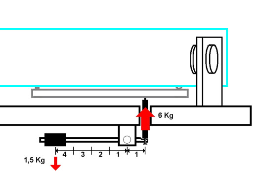
The counterweight must counterbalance the mass of glass that it pushes. In the case of one 18 points with 3 astatic levers, each lever pushes 1/6 of the weight mirror. If there are 6 kg to counterbalance and that the level ratio is 4, then a counterweight of 1,5 kg is good. (kg = kilogram)
| |||||||||||||||||||||||||||||||||||||||||||||||||||||||||||||||||||||||||||||||||||||||||||||||||||||||||||||||||||||||||||||||||||||||||||||||||||||||||||||||||||||||||||||||||||||||||||||||||||||||||||||||||||||||||||||||||||||||||||||||||||||||||||||||||||||||||||||||||||||||||||||||||||||||||||||||||||||||||||||||||||||||||||||||||||||||||||||||||||||||||||||||||||||||||||||||||||||||||
| |||||||||||||||||||||||||||||||||||||||||||||||||||||||||||||||||||||||||||||||||||||||||||||||||||||||||||||||||||||||||||||||||||||||||||||||||||||||||||||||||||||||||||||||||||||||||||||||||||||||||||||||||||||||||||||||||||||||||||||||||||||||||||||||||||||||||||||||||||||||||||||||||||||||||||||||||||||||||||||||||||||||||||||||||||||||||||||||||||||||||||||||||||||||||||||||||||||||||
General remarks: It is possible to adapt an astatic mirror on to an existing telescope but it is always harder to do this than to incorporate it at the beginning of the project. To made an astatic mirror cell is not much more complex than manufacture a traditional mirror cell of a Dobson. The necessary tools simple since a hacksaw and a drilling machine are all that is necessary to enable the average ATM to do most of the job.
| |||||||||||||||||||||||||||||||||||||||||||||||||||||||||||||||||||||||||||||||||||||||||||||||||||||||||||||||||||||||||||||||||||||||||||||||||||||||||||||||||||||||||||||||||||||||||||||||||||||||||||||||||||||||||||||||||||||||||||||||||||||||||||||||||||||||||||||||||||||||||||||||||||||||||||||||||||||||||||||||||||||||||||||||||||||||||||||||||||||||||||||||||||||||||||||||||||||||||
| |||||||||||||||||||||||||||||||||||||||||||||||||||||||||||||||||||||||||||||||||||||||||||||||||||||||||||||||||||||||||||||||||||||||||||||||||||||||||||||||||||||||||||||||||||||||||||||||||||||||||||||||||||||||||||||||||||||||||||||||||||||||||||||||||||||||||||||||||||||||||||||||||||||||||||||||||||||||||||||||||||||||||||||||||||||||||||||||||||||||||||||||||||||||||||||||||||||||||
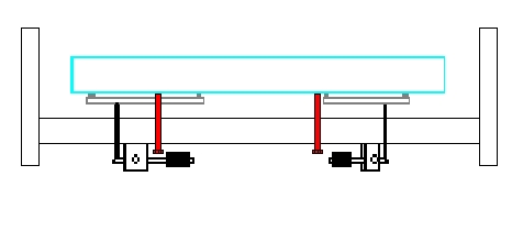
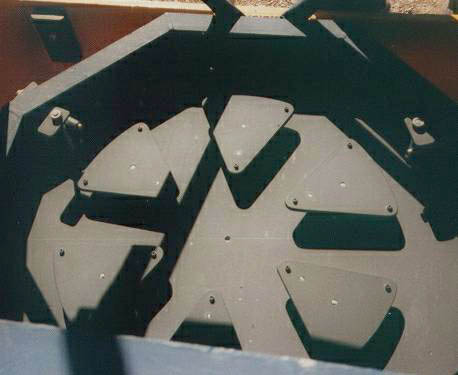
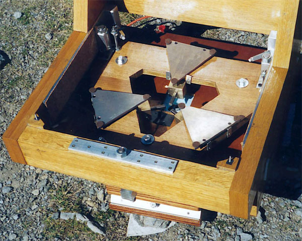
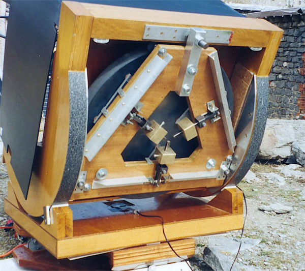
Shown are examples of a mirror cell with 18 points in mixed mode showing the triangles of floating and the astatic supports. Adjustments Adjustments of the mirror cell were made using the whole scope while doing the star-test in order to tune it. It is the mirror cell made for the 560 mm described on this website.
| |||||||||||||||||||||||||||||||||||||||||||||||||||||||||||||||||||||||||||||||||||||||||||||||||||||||||||||||||||||||||||||||||||||||||||||||||||||||||||||||||||||||||||||||||||||||||||||||||||||||||||||||||||||||||||||||||||||||||||||||||||||||||||||||||||||||||||||||||||||||||||||||||||||||||||||||||||||||||||||||||||||||||||||||||||||||||||||||||||||||||||||||||||||||||||||||||||||||||
| |||||||||||||||||||||||||||||||||||||||||||||||||||||||||||||||||||||||||||||||||||||||||||||||||||||||||||||||||||||||||||||||||||||||||||||||||||||||||||||||||||||||||||||||||||||||||||||||||||||||||||||||||||||||||||||||||||||||||||||||||||||||||||||||||||||||||||||||||||||||||||||||||||||||||||||||||||||||||||||||||||||||||||||||||||||||||||||||||||||||||||||||||||||||||||||||||||||||||
It's a 12-points cell with 3 fixed points without kneecaps, and 3 triangles on a kneecap and lever. The transmission of the effort is carried out by metal blades. Their first image was horrible because of a big astigmatism. After having removed the mirror of its support, it was easy to see that the mirror was not in contact with the 3 fixed points. After adjustments of these points to bring them into contact with the back of the primary mirror, the 3 counterweights of levers were brought to a point close to their minimal effect, where they generate less force. As the force of the levers is then insufficient, the mirror is support only by the 3 fixed points. At the eyepiece, there is then a triangular star. To see whether it is necessary to add force to levers, we remove all the push of the counterweight by raising them manually and we note that this triangular shape of the star image was worse. That means that the level didn't push enough, so we added some distance to the counterweight (same amount at the same time) and we saw the triangular shape slowly disappear. Needless to say that these operations are much easier to do with two people! This experiment is very interesting because it is incredibly easy to see how much a mirror, even a thick on, can be easily stressed by a small amount of uneven pressure. For a mirror cell with two circles of triangles, the procedure is the same, one finishes simply by the adjustment of the central circle, which is used to adjust the spherical aberration.
| |||||||||||||||||||||||||||||||||||||||||||||||||||||||||||||||||||||||||||||||||||||||||||||||||||||||||||||||||||||||||||||||||||||||||||||||||||||||||||||||||||||||||||||||||||||||||||||||||||||||||||||||||||||||||||||||||||||||||||||||||||||||||||||||||||||||||||||||||||||||||||||||||||||||||||||||||||||||||||||||||||||||||||||||||||||||||||||||||||||||||||||||||||||||||||||||||||||||||
| |||||||||||||||||||||||||||||||||||||||||||||||||||||||||||||||||||||||||||||||||||||||||||||||||||||||||||||||||||||||||||||||||||||||||||||||||||||||||||||||||||||||||||||||||||||||||||||||||||||||||||||||||||||||||||||||||||||||||||||||||||||||||||||||||||||||||||||||||||||||||||||||||||||||||||||||||||||||||||||||||||||||||||||||||||||||||||||||||||||||||||||||||||||||||||||||||||||||||
Thank you to Luc Arnold for his invaluable assistance and the provision of the table on points of support, and to David Vernet for the photographs which illustrated this article. | |||||||||||||||||||||||||||||||||||||||||||||||||||||||||||||||||||||||||||||||||||||||||||||||||||||||||||||||||||||||||||||||||||||||||||||||||||||||||||||||||||||||||||||||||||||||||||||||||||||||||||||||||||||||||||||||||||||||||||||||||||||||||||||||||||||||||||||||||||||||||||||||||||||||||||||||||||||||||||||||||||||||||||||||||||||||||||||||||||||||||||||||||||||||||||||||||||||||||
see also | |||||||||||||||||||||||||||||||||||||||||||||||||||||||||||||||||||||||||||||||||||||||||||||||||||||||||||||||||||||||||||||||||||||||||||||||||||||||||||||||||||||||||||||||||||||||||||||||||||||||||||||||||||||||||||||||||||||||||||||||||||||||||||||||||||||||||||||||||||||||||||||||||||||||||||||||||||||||||||||||||||||||||||||||||||||||||||||||||||||||||||||||||||||||||||||||||||||||||
|
|