|
Technical
review
|
|
|
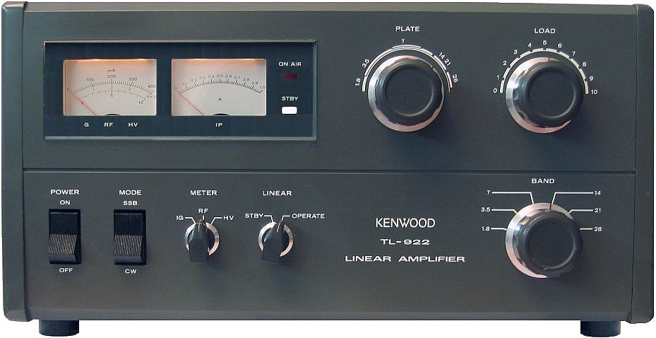
The
Kenwood TL-922 amplifier, 850 W output. |
How
to select a tube HF amplifier ? (I)
Imagine
that all your ham shack is invaded with rigs and accessories, that
your antenna, beam, vertical or wire is
performing, proved by your hundreds QSLs received from far DX
stations. But sometimes, during pileups or when propagation
is closed you have difficulties to work some remote stations or to
get good reports exceeding 53-55. On your side you hear them all,
not always loudly, but at least 53 or with a strong intelligibility or QRK.
The
need and the fashion
If
you really experiment problems in working far stations or pileups
although you are using efficient gears but at first sight not so
performing as expected, in this case the last thing to install beside your 100 W PEP barefoot
transceiver is well a good amplifier, up to your class limit, 400 W,
1 kW or more, depending on your national regulation. Good news, you
will tell me ! Indeed, but at the condition to use it properly. What
we are going to review.
In
all other circumstances, if your RTX is not equipped with performing
filters to reduce QRM, if your antenna yield a low gain or is
omnidirectional or erected very low above the ground, improve first
the efficiency of your equipment instead of looking for the last
novelty. For the same price or even cheaper, it will be more useful to improve performances
or your transceiver and antenna than using a linear amplifier. In all cases adding an amplifier to
your current installation will probably not help you much in working
far DX stations that arrive 53 or not at all to you.
But
I have never said either that an amplifier might replace a defective
antenna. Far from me this idea. Do never use a high power to
compense the poor performances of an antenna. This is indeed the
best way to create QRM or get serious troubles if your installation
(cabling system, SWR-meter, power supply, etc) is unable to sustain
such power, thus high currents. Build or purchase first a better antenna !
Improve first
your antenna system in reducing the ground effect, use a low loss
coaxial (RG-213, Belden RF-9913, Aircom, etc), try to get an
excellent VSWR on the line, as much features
that, once optimized, will increase the efficiency of your
installation. Then add some filters (Collins, etc), change
maybe your transceiver for a more performing model and at last, after
one year of experimentation, see if an amplifier is really
necessary.
This is
a wiser advice than using an amplifier at all costs
and be unable to use it properly or to hear your correspondent. The
impertinent reader will say that "for lack of a big gun you
need a big mouth !" Mm... Indeed. Without more know-how, answer
first to the question : for
what usage do I want imperatively an amplifier ? Isn't there a less
expensive and better solution ? Then, be aware that a
bad manipulation can quickly burn your P.A or produce dangerous side
effects. Here are some examples.
If
your transceiver last stage is badly matching your amplifier input
specifications, you have all chance to burn your P.A. The Kenwood
TL-922 amplifier for example must be driven with an input power
ranging from 80 to 120 W PEP, no less no more. But if you want to
preserve the lifespan of both your transceiver last stage and
amplifier, drive this latter with 80 W in. Optionally reduce a bit
the load to get less output power (with sometimes a higher SWR).
Then, in
tuning not correctly your amplifier you will make QRM over 10 kHz or
more around your frequency, without working more stations but in
disturbing a lot of amateurs.
If you place your antenna system too
close to your shack, say in the first 15m away (50'), using 1 kW PEP you
are to the edge of the security distance requested when using HF
systems emitting a strong electromagnetic field
(e.g.. a beam offering a gain of 8 dBd, transmitting 5 kW EIRP generates a max field intensity
of ~27 V/m).
The solution is to place your antenna over 20m away (67') from any human
being. With a mast 10m high (33'), you won already 10 meters.
At last, without
knowing exactly how powerful can be your signal, if you position your
antenna straight to the TV yagis erected by your neighbour, you
will quickly receive his visit.
These few examples of behaviours
do not respect either the ham spirit
nor your health and are not
very useful. And all the more that an amplifier is often expensive
and bulky, and requires some basic knowledges of the subject if
you want to respect the other hams working on the air as well as the
regulation. So think about these potential problems at twice before
investing in such an equipement.
If
you are convinced by the utility of an amplifier here
are some advice if you decided to buy or build a tube(s) linear
amplifier to work in HF.
I took the example of a kW class amplifier as it is
widespread in the ham community among hams who have the chance to be
allowed to use so high powers. I shall describe all its internal
components and their characteristics, as well as features to check
with care. Basics considerations are universal and can of course be
applied to all other models, working in HF, VHF, UHF,
whatever, doesn't matter, with the exception that in
centimetric bands, high power entail new technical
constraints on electronic components and wiring systems.
Kilowatt-class amplifiers
|
|
|
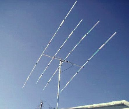
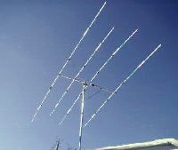
You will
profit at best of your amp if you work with a directional
antenna, like this five-bander beam Mosley TA-33-JR-N. |
Why using so much power ? This is a pertinent question. But don't be
offended by the ham telling you that you have a big mouth, because
there are some good objective reasons in using such a power. As said
some Old Timers, you might answer to this people, "you know kid,
the live is too short for QRP, go QRO !". But enough of this
joke.
Going up
from 100 W to 1000 W PEP, the
power ratio is 10 and looks high if not huge. But knowing that you
add only 3 dB each time you double your power, 1 kW output produces
only a 10 dB power gain on the S-meter, what is not really important.
However your QRK will be much improved and your correspondent will
have please to hear you in better conditions, mainly if you work
with a directional antenna, in which you can concentrate all
your RF signal.
In
all quality tubes amplifiers (i.e. Ameritron AL-1200X, QRO HF-2000, Kenwood
TL-922, etc) removing the cover we are often impressed with the design, the few
components but how big, the care and finish of the work brought up to
the band-switch and cosmetics. All high-end kW amplifiers display
big, strong and rugged accessories, large coils, big capacitors,
heavy toroidal transformers, big choke, for short all is big and
seems to offer an excellent quality. Even the vernier, switches and
potentiometers are big but all them move softly without interplay,
like professional or military material, specially the Kenwood TL-922.
Looking
closer inside the amplifier, between the large components there is a large control board
full or small colored active or passive components. It provides low
voltage bias, screen trip and control circuitry. In addition several
smaller circuit boards complete this installation, like the high
voltage rectifier board, the screen supply board, the RF I/O board,
the ALC circuit board and the metering board. Let's
see in detail each of these components.
|
Voltage,
current and impedance in amplifiers
We
can see a linear amplifier as a "black box"; it doesn't matter what goes on inside.
Whatever the band used, most,if not all linear amplifiers have 50 W
input and output impedances. Used with a 100W emitter, a kW linear should have a power gain of
10 dB. |
|
If
it is a 12V solid-state linear, the voltage levels will be
low; at the device terminals the output voltage is
no more than about 20V PEP, but the RF current will be
high, up to 80A peak for a 500W amplifier. The impedance will be rather low,
less than 1W.
If
it is a valve linear, working at about 2 kV anode supply, the
RF voltage at the anode could be as high as 4 kV PEP. |
|
At
so high voltage the RF current will be less than 100 mA RMS,
the impedance being around 16 kW.
In
each case, the input impedance will be practically of a similar value.
The input and output (tuned) circuits will
take care of matching these values to 50 W, because your
RTX and your antenna need to "see" that impedance
to offer as less as loss as possible and the lowest SWR. |
Generally,
such a device will (at lower frequencies at least) have only
a single valve or transistor or tube as an amplifier. Depending on
the design, it may have one or more additional active
components providing bias, switching or even a receive
pre-amplifier. In the case of a tube amplifier there is no
pre-amplification; transmitting power tubes ensure
themselves the power gain. |
Power
tubes
In
kW linear amplifiers RF power tubes are still made of a glass
envelope, a design disused by manufacturers since the middle of years
90's (1997 at Eimac). Most metal/ceramic tubes are also discontinuing
(i.e. 8873, 8874/3CX400A7, 8875, 3CX1200A7, D7, Z7, ...) as well as
most tubes made in Russia, Chzek or China. The last tubes still in production
until 2020 or later are 3CX1500A7/8877 triodes and alike made by Eimac/PCI
and the Svetlana production. Many other tubes which production has been interrupted are however still
available as spare (see links on the last
page).
But
until recently, most Russian tubes were considered as not reliable,
and the rumor extended deep among the ham community who rarely
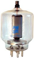
accepted to buy such tubes. A Tesla 8877 triode for example was not
consider as reliable as the same model manufactured by Eimac, like
the one displayed at left. Idem
with the 8802 aka 3-500Z.
In some cases the filament of these
tubes blow out after a few dozen hours of work or they simply refused to switch on due to
mechanical problems. But on the other side I can confirm you that
the same tube manufactured by Eimac shown also
mechanical problems.
When we know how high is their price and the
so-called quality control,
such problems are inacceptable. Of course such tubes are covered
with a warranty, but when this problem occurs 2 years after your
purchase, it is no more question to ask for a standard exchange...
With
these positive and negative experiences, nowadays there are two ways
to select a tube amplifier, for short the expensive and the cheap
one; in other words selecting high or low quality tubes. Let's explain
this idea.
For
decades quality tubes were manufactured by Eimac, RCA or Westinghouse
among others U.S. companies. But for some years similar tubes but twice,
three or... even ten times cheaper were manufactured
in Russia and eastern states.
Most of these "Rusky" tubes
(8877/3CX1500A7, 8802/3-500Z, etc) are always available and reliable, as
performing as their U.S. counterpart. So if you have the choice and
some money left, you can purchase an expensive 8877 tube and alike
made by Eimac, which production is ensured for some decades. This is
an excellent warranty in case of failure.
|
|
|
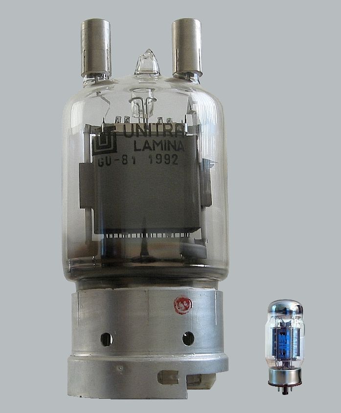
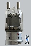
A GU-81
pentode, 26 cm tall, almost 1 kg, it develops 600 W for... $15 without its
socket. Like me you can use it as decoration item ! |
The positive side is that you can buy several of these
reliable tubes together with your amplifier at the time of purchase.
But if you want to spare some money you can consider purchasing
their cheap counterpart made in Russia or even at Eimac. You
do also an excellent choice because this is a plentiful tube and you
can blew out several of them without be brough down by this
loss.
The
drawback of purchasing an expensive Eimac tube is that in case of
failure you have to break your moneybox and invest between $400-1100
to replace it... With a tube manufactured in the East in case of
failure you will only pay between $170-350 plus charge (about $40
for an express oversea shipment) ! With the
Svetlana 3CX800 tube for example the street price can even drop as low as $50
instead of...$525 in buying a similar triode at Eimac ! Of course I
cannot assure you the quality of this bargain, but is this necessary ?
To
read : How to
preserve your tube lifespan ?
Make
a 3-kW linear with 2x GU-81M (schematic in PDF),
EX8A
If
I cannot take the decision at your place, objectively you have to select
a tube that first suit your needs, which specifications match the
ones of your amplifier (in terms of power, current, temperature, fot
short its comptability).
Then you have to select an amplifier which transmitting tubes will still be available in 10 years or
later or, more secure, be able to invest today in 2 or 4 spare tubes. If
these tubes can still be purchased today at a reasonable price, in
one decade or two, they could reach a high price, and be much more
expensive than today. Of course you will not benefit of the one year
or two years of warranty offered with these tubes in stocking them in your drawer
but at least you have the "warranty" to be on the air
today or later at full power.
At
last select also your tube according the amplification
class you desire. No positive grid current, high
plate-dissipation, no regulation need ? Then select a Class AB1 amp.
Need a high efficiency associated with a high amplification factor,
then select a Class AB2 amplifier.
|
Gain and efficiency
One
say that a class AB amplifier can only turn about 50% of its
input power into radiated power. The rest of the input power
that cannot be radiated is lost as heat. This explain why an
amplifier rated at 1 kW PEP DC input develops only 0.5 kW
PEP output. In the same way a device offering 70% of
efficiency loses only 30% of its input power as wasted heat.
In
this matter the term "gain" for an amplifier can
be confusing. Here is an example compared to
"efficiency" :
An
amplifier driven with 100 Watts input develops 500 Watts
ouput to the antenna as radiated power. Therefore its gain
is 500/100 = 5.
But
its "efficiency" is different. Its efficiency is 1000
Watts input for 500 Watts out as radiated power. In others
words that represents 50% efficiency for its power device,
tube(s) or transistors.
But
for the amplifier seen as a whole, the total power into the
entire amplifier is 1000 Watts input to its final, from the
main in which I plugged it into *plus* the additional 100
Watts input to the drive (base) circuitry coming from the
transceiver. So the efficiency for the amplifier as a whole
is :
500W
/ (1000W + 100W) = 45.4% overall.
But
for the station as a whole, the total power into the
transceiver is 200 Watts for 100 Watts output. So, overall,
the station's true power efficiency is only :
500W
/ (1000W + 200W) = 41.7%
|
|
RF
circuit
Vacuum
tubes operate at high voltages (and moderate currents); typically, a
power amplifier stage requires an RF anode load resistance of
approximately 2 kW to get optimum efficiency. Therefore the
most visible and important part of an amplifier is the famous
"RF tank circuit" named after the large tank coil that
stands in the middle of this module, near the plate choke. After the transmitting tube,
the RF tank and in a lesser extent capacitors determine
the overall efficiency of the amplifier.
 |
 |
|
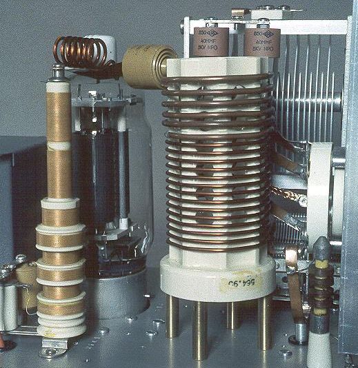
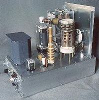
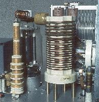
Closeup
on the Wingfoot 813 amplifier made by Dr.
Greg Latta alias AA8V. At left of images, the plate RF choke
(the yellow "chimney") and in the middle the
large cylindrical tank coil here wounded around a
ceramic cylinder. At the foreground and to the right
is the small antenna RF choke. |
|
Tank
coil
The
tank coil sometimes wounded around a large ceramic cylinder is made of a copper
tubing (or wire), 0.5mm tick or larger. To work on the 160 meters
band, manufacturers prefer using toroid cores to keep the coil in a
reasonable size, but this solution offers sometimes problems if its
diameter is too small or badly insulated.
A
performing toroid core should display a diameter over 50 mm
(2") made of 3x T-200-2 cores, red mix type. The coil should be a
12 ga (inner Ø2.07 mm) Teflon insulated wire or at least made of 1.25 mm polyurothane grade
1 (PUR1) insulated winding wire. It should be wrapped in glass tape, stacked on 3 deep.
At last the core should be isolated from the other components and placed
away from any metal to prevent arcing.
Next
chapter
Capacitors
|