|
|
|
Transmission lines
SWR, the radiation resistance We often hear the expression "my antenna displays an SWR of such a value". Amateurs saying that do not understand how work their antenna and its associated feed line. The SWR is not an antenna property but rather a property of the transmission line. An antenna displays only an impedance (and other characteristics) that varies with the frequency. Contrary to the idea sometimes expressed by amateurs, the impedance matching of your antenna has few effect on your signal and a mismatch does not create RFI. The SWR, that stands for Standing Waves Ratio, expresses the impedance matching between your feed line (or the transceiver) and the charge (the antenna), in other words the radiation resistance of your antenna system to not confuse with DC resistance. Impedance of an antenna refers to the ratio of the voltage field to the current field flowing within an antenna. On a well tuned aerial which feed line displays an SWR ratio of 1:1 all the RF energy is transmitted from the RTX final amplifier to the antenna tuner and then through the feeder to the antenna. In this configuration the current is equal at any point of the line and your antenna works properly. If the SWR increases for any reason, stationnary waves appear; in HF that means that a part of the RF energy you sent to the charge is waste as heat before reaching the antenna, mostly in the feed line. Note that using very low loss feed lines, in HF and in a lesser extent in V/UHF, this waste due to a high SWR is very weak. In a perfect matching system displaying a SWR 1:1, which output is constitued of a dummy load, all the power arriving to the charge in fully absorbed (converted in heat). If this load is an antenna this energy is totally radiated into space. If the system is not perfectly matched the larger part of the power will be absorbed by the antenna resistance but a few percents will be "reflected", in fact added or substracted in the line. The ratio of these peaks (high/low currents or induced voltage) represents the SWR. Practically the SWR is altered when there is a mismatch of mating the 50 Ω feed line to the higher impedance of your aerial. In such conditions the extent of the antenna radiation pattern that we will see on the next page and representing the concentration of its signals can be modified displaying a decreasing of its maximum range. Without other consideration, the consequences of a high SWR are not as severe as we could expect and this potential loss will not interfere with TV receptors and will not create RFI as we sometimes hear or read here and there.
To watch : Digital SWR Power Meter MFJ-849
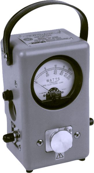
Imagine an antenna system showing a SWR 6:1, thus 50% of reflected power (not the same as 50% or 3 dB of signal loss). What is the impact of this SWR on the power of your signal ? These 50% of reflected power due to the antenna system mismatch go back to the AT-tuner (adapter) and are reflected again to the antenna, in phase with the incident wave. We must then distinct two cases : the adapter is matched or mismatched. If systems are matched, when impedances are combined, conditions of the "maximum power transfert theorem" are met in any point of the line linking the adapter to the antenna. All the reflected power going back from the antenna is resent in phase to the antenna. In this case, the only lost power is the one due to the double crossing of reflected power in the feed line (once descending, once going up again). We can demonstrate this using a no-loss feed line : for 100 W sent into an adapter using a matched line showing 50% of reflected power at the feet of the antenna, 200 W are emitted and 100 W are reflected (100/200 = 0.5). Thus the emitted power is 200 W - 100 W = 100 W as well. This measurement can be confirmed using a simple Watt-meter like a Bird. For the theory, read Walter Maxwell's book "Reflections". If the adapter is not matched, conditions of the maximum power transfert theorem are not met, matching is not satisfying, and the functionning point (DC) of the final tube or transistor is displaced (by "good functionning" we mean the required charge to get a minimum input current for a given feeding voltage). If matching is uncomplete, the charge will not be optimum, the functionning point will move and the current will increase (the tuning abacus follows a kind of parabolic curve). Using e.g. a Pi-adapter with a tube transceiver, we can easily note this minimum of plate current. Many amateurs believe that when power is reflected, this one will go back up to the final amplification stage where it will dissipate, increasing the risk of damaging electronic components. This rumor is completely false ! Telecom engineer Jacques Culot, ON5MJ reminds us that in this example there is not the slightest HF dissipation in the final stage. The sole effect of the reflected power associated to a lack of matching is that the final stage will dissipate still a bit more DC. Indeed, a mismatched adapter will prevent the final stage to generate the maximum power, and thus will feed the antenna with a reduced power.
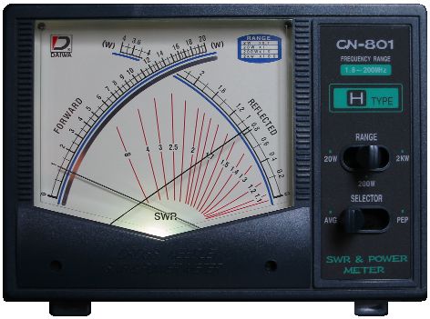
This phenomenon is easier and more intuitive to understand using vintage tube amplifiers as we saw directly effects of the matching on the current-meter. In modern transistorised transceivers, manufacturers are no more concerned by matching impedances, and do no more include adapter in their emitter (it is cheaper and more compact) supposed linked to a 50 Ω load. But in the field this condition being far to be met, the increase of collector current had had to be limited using a device. Circuits measuring the SWR were inserted, reducing gradually the power. We can also put the adapter at the end of the emitter, the matching being established in measuring the maximum transmitted power as we can no more access to the final stage. At the end be come back to the previous system : the matching device is included in the rig. Today this tuning is automatic and loss in the adapter are important because specifications of components are too tight. A high SWR will however have a bad impact on your RTX PA transistors that will see their charge going away from the expected matching value. In the worst cases, you can damage them due to the heat dissipated in circuits. A high SWR increases the attenuation on higher frequencies too. Practically for a SWR 1:1 you loose 0.4 dB at 3.5 MHz and 1.1 dB at 28 MHz. But for a SWR 5:1 you only loose 0.8 dB on 3.5 MHz but 2.5 dB at 28 MHz. This latter represents nearly half of your emitting power ! However to your DX station, his S-meter has probably not recorded the change when we know that a 100/1000 W power ratio only produces a 10 dB change on the S-meter (3 dB each time you double your power), nothing else than 1 more point on his display ! The antenna impedance can be measured using modern RTX that often provide a built-in Antenna tuner. Otherwise you can use an external reader know as a Noise or SWR bridge to fit on the coaxial line. The SWR-meter After your transceiver and your antenna, it is more than necessary that you own an external SWR-meter or wattmeter. It will allow you to know exactly what power radiates your antenna system. A dummy load suited to your emitting power is also interesting to get to make some emission tests without perturbating the bands with useless vocalizes and tunes... How to select a good SWR-meter or wattmeter ? A good SWR-meter like the Daiwa CN-801 serie displayed below costs about 140 €. It must be able to sustain the highest power you might use (1 kW PEP or so) and be adapted to the right bands of frequencies. They are models working on HF, VHF, HF/VHF or V/UHF bands. Most recent models display forward, reflected power and SWR simultaneously thanks to a cross-needle display. To calculate the SWR, some models request however to flip a switch or let you calculate the SWR yourself.
Your meter should be able to display RMS (average) and peak values. Indeed in a usual conversation in SSB the average emitting power of your voice can be relatively low (say below 40 W over 100W PEP) but during short periods of time and quite regularly you can double this power and exceed 80 W when using sibilants. These bursts of power are interesting to monitore when your transmitter is connected to a linear amplifier to check if you do not "overload" your antenna system if you suspect a bad tuning. In addition, peak-readings SWR-meters can be active or passive. "Active" means that the peak reading is electronic, and amplified before to be displayed. These meters must be powered, usually in 12 V. As expected they are the meters the most accurate, contrarily to passive meters that use an unamplified meter-damping circuit to read the peak value. Most need however to be powered, not because they are active but simplier to light the cross-needle display. Some old meters still include additional knobs to adjust the load reactance and resistance. They are very accurate but a bit longer to set. Some desk models have also to be calibrated according your peak emitting power (100 W, 1 kW, etc) but most are today autocalibrated and they request no adjustment. You read and appreciate the values... At last some SWR-meters are very small, in both size and readings, suited for QRP operations, other are as large as a laboratory device, attracting, suited to operate on the amateur's desk. Some amateurs complain sometimes of forum to the fact that most "customer SWR-meters" are unaccurate. They are wrong. In fact most passive readers are accurate for what they cost and all are able to read the power and give the SWR within 3-10 % of error. Probably that in practice amateurs are not really interesting in knowing if their transmitter is emitting 80 or 88 W but rather if all the input power is well radiated by the antenna. The active readers (e.g. Palstar WM150) are of course the most accurate but here also the combined HF/VHF readers suffer of a lack of accuracy over 150 MHz. To
watch : Ham Radio Basics: Why You Need a SWR Meter How to Use an SWR Meter: standing wave ratio meter - guidelines & tips
Antenna tuner Instead of purchasing an external SWR-meter or a wattmeter you can buy an external antenna tuner that will help you to match the load according the working frequency. It will not tune your antenna at all, but transform the impedance to provide your transmitter with the proper load of 50 Ω. Although more expensive than a SWR-meter, an external antenna tuner is really useful because modern transceivers have a narrow range of impedance matching close to 50 Ω, and are unable to match the high impedance of many wire antennas that are ranging between 10-600 Ω or more. Even a so-called 70 Ω dipole antenna can see its impedance change as soon as you modify its length, its height above ground or the length of the parallel-wire feed line. Weather conditions also affect these values. Hence the interest of using an antenna tuner in all circumstances.
If your transmitter built-in tuner is able to match SWR mismatches up to 2.5 or 3:1, beyond this value you couldn't use your emitter, and surely not if you use an amplifier. Therefore today we find an external antenna tuner into most shacks at one time or another. Some have to be manually tuned but others are automatic, analog or digital, and offer you in all circumstances the lowest SWR and losses. Some are able to handle 1, 2 or 3 kW output or even more. Some tuners can read settings of your RTX and save them in memory. The best models tuned your antenna system in about 5 seconds whatever the band or the antenna design. How that works ? An antenna tuner is far different from a SWR-meter. This is an active device that needs to be manually tuned (at least the manual models). Opening the case of an antenna tuner, you will see two large capacitors and an inductance switch (or a roller inductor) connected outside to a rotary switch. Labeled "ANTENNA" and "TRANSMITTER" on the front panel, these capacitors must be adjusted until you hear the loudest signal on your receiver. This is simple and efficient. However, be aware that the coil used in an antenna tuner cannot withstand much power. As the load impedance increases, losses will get higher. If you system can still work with 50 % of 1 kW in the antenna tuner, 500 W will be dissipated as heat in the tuner coil. A high-power antenna tuner will probably supports such losses, but be careful working with high SWR and ordinary tuners because a tuner failure can always happen. In the worst cases, in presence of high SWR, high power (current) and and moisture you can even burn the coaxial terminals on the line. Note that many antenna tuners of the old generation (say before 2000) are unbalanced. If you work with a balanced antenna system you probably use a balun to match impedances that can vary quite much according to the frequency. In the worst conditions, if you experiment a high SWR on the line, the lost energy can damage the balun, all the more using high power. Therefore several manufacturers (e.g. Palstar, MJF or E.F. Johnson) sell for some times balanced antenna tuners to prevent these possible damage to balanced antenna systems.
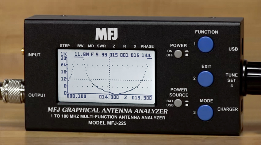
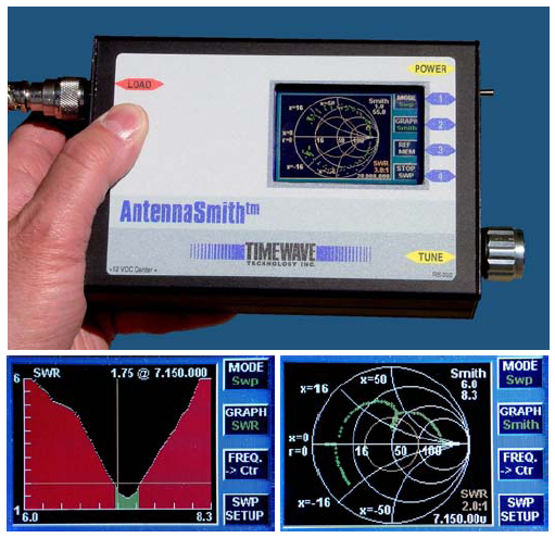
If most use a dual T or L section, some models like Palstar used an insulated unbalanced/balanced circuit to get the same result with excellent figures. Palstar AT1500BAL ($695) and MFJ-974H ($199) models perform the best. The two models get a matching in most conditions including for SWR 32:1 between 160 m and respectively 20 and 10m band and sustain 1.5 kW and 300 W PEP. Like for SWR-meters, the price of an antenna tuner is proportional to its performances, some being for example unable to match SWR over 2:1 on 160 m. For a HF cross-needle model supporting 3 kW PEP the price is ranging between $330 (MFJ) to $600 (Ameritron). A "laborarory" grade SWR-meter can be as expensive. These two gears being very important to check your emitting conditions, here is a list of very appreciated SWR-meter and antenna tuner manufacturers. Most models sold in the past by Icom, Kenwood or Yaesu are today discontinued but they are always available on second-hand. A must for your shack ! Low SWR but no efficiency Imagine that you want to work an extra band on which your antenna in not tuned because it is not cut for. Take a simple example with the well-known 31.1 m (102') G5RV multi-band dipole using a ladder line and a balun 4:1 to match the impedances. In this length and without modifications you cannot use it on the 160 m band. Why ? What's the matter if we try... (To never do in the field please). Here is the answer. Using a good antenna tuner you can reduce the SWR on that band until to reach SWR 1:1 or so as displayed at left on the transceiver S-meter. At first sight all is fine, the antenna resistivity is not absorbing the power, and you might transmit a strong RF signal on 160 m. But in the field you observe that nobody answers to your call... If you try to transmit in such conditions, this is unfortunately misinterpreting how work an antenna and a resonant circuit. In fact you have indeed a SWR 1:1 between your transceiver final amplifier and... the antenna tuner, often built-in, but not further. The SWR-meter built-in in your RTX has not read the SWR on the feed line to the antenna where your signal should radiate in the air. If you do this measurement using an external SWR-meter like on the picture displayed at left you will discover than the SWR reaches huge values, say over 200:1 if not infinite trying to work on 160 m with a multiband dipole 33 m long, not suited for this band. Why so ? In this particular case you are trying to feed a dipole antenna which is much shorter than 1/2-wavelength. If we trace its complex impedance (Z = R±jX), in other words the resistance part against the reactance part of the antenna impedance as displayed at right, for 0.2λ (below left of the graph) we observe on the curve that R = 20 Ω, X ~ 300 Ω (what writes also R=20-j300); on 160 meters or 0.183λ, X > 1800 Ω... the antenna presents a highly capacitive load to your tuner. Your antenna system is not resonant.
If your tuner does manage to match this load, you will get an extremely high SWR on the feedline, over 160:1 in usual conditions (on most external SWR-meters the needle will move to "∞"), and very high currents will flow in the tuner's inductive component(s); your transmitter's power will be dissipated as heat due to the resistive losses in the feed line and in the tuner inductor(s). The efficiency of your antenna will be near 0 due to losses in the feed line that can exceed 35 dB or 6 S-points ! Not the single milliwatt will be sent to your antenna, although your built-in SWR reads 1:1... In fact your both SWR-meters work perfectly right but... you don't ! Be very careful in trying to operate this way. In the field, trying to drive a too short doublet might lead to a complete destruction of the antenna tuner : the heat dissipation can crack toroid cores, melt the plastic forms in roller inductors, etc. In working on the air long times in such conditions your can also damage your PA transistors, and this is an expensive module to replace. The plastic or bakelite of your PL or BNC connectors can also burn and produce arcing. These accidents are very serious damages for your installation, what explains the reason for which I didn't recommend you to make this test before going on the air ! NB. The curves indicating an additional line loss due to standing waves implicitly assume an ATU at the input to the transmission line with a complex conjugate impedance providing a perfect impedance match to the source. In other words the loss due to the antenna mismatch is transformed into the “additional loss” (read the below PDF file for more information). On the contrary as soon as you extend your aerial to reach 1/2λ on the working frequency (in this case extending its length to 84 m long or working on the 80 m band) you could read R = 75 Ω, X = 0 Ω. Your antenna is purely resistive, offering in best cases 100 % of efficiency; you have a resonant circuit and you can feed it without loss ! But if you calculate the efficiency of a dipole 31.1 m long on 160 meters (1.9 MHz), you will get an overall radiating efficiency of... 1.4 % only ! For dipoles, you can also simulate other lengths and impedances downloading the excellent and free program DIPOLE3 created by G4FGQ. This routine running in a DOS box analyses performances of any dipole, of any length, any wire diameter, placed at any height, and for any length of any type and combination of feed lines. Once you get a solution you can do varying these factors. The resulting values displayed on screen are the efficiency, SWR, loss, and their counterparts in dB or S-units (S-points). Also calculated are L and C component values of L-network to match to 50 Ω. At last, since 2005 Timewave sell an antenna impedance analyzer model "TZ-900 AntennaSmith" ($999.95) displayed above. It is a small box operating between 0.5 and 60 MHz able to simulate on its small TFT screen SWR graphs and Smith charts in full color. It is a pity that it is so expensive. For more information Input impedance and SWR (on this site) Understanding SWR by Example (PDF), K5DVW The Effect of Load VSWR on Transmission Line Loss (PDF), Richard Kinsley Ham Radio Basics: Why You Need a SWR Meter, YouTube How to Use an SWR Meter: standing wave ratio meter - guidelines & tips, YouTube SWR-meters, wattmeters and antenna analyzers: Digital SWR Power Meter MFJ-849, YouTube Ameritron, Array Solutions, Autek, Bird, Daiwa/NCG, Diamond MFJ Enterprises, PalStar, Telepostinc, Ten-Tec, Timewave, Yaesu Smith charts Smith Chart Calculation (PDF), ARRL The Smith Chart: An ‘Ancient’ Graphical Tool Still Vital in RF Design, Digi-Key XLZIZL, AC6LA Smith Chart Calculator (Java software) Antenna tuners Alpha Delta, Ameritron, Kenwood, LDG Electronics, MFJ Enterprises Nye-Viking, PalStar, Ten-Tec, Tokyo Hy-Power, Vectronics, Yaesu Reviews on eHam: SWR-meters and Antenna tuners.
|
||||||||||||||||||||||||||||||||||||


