|
|
|
All about Transmission lines
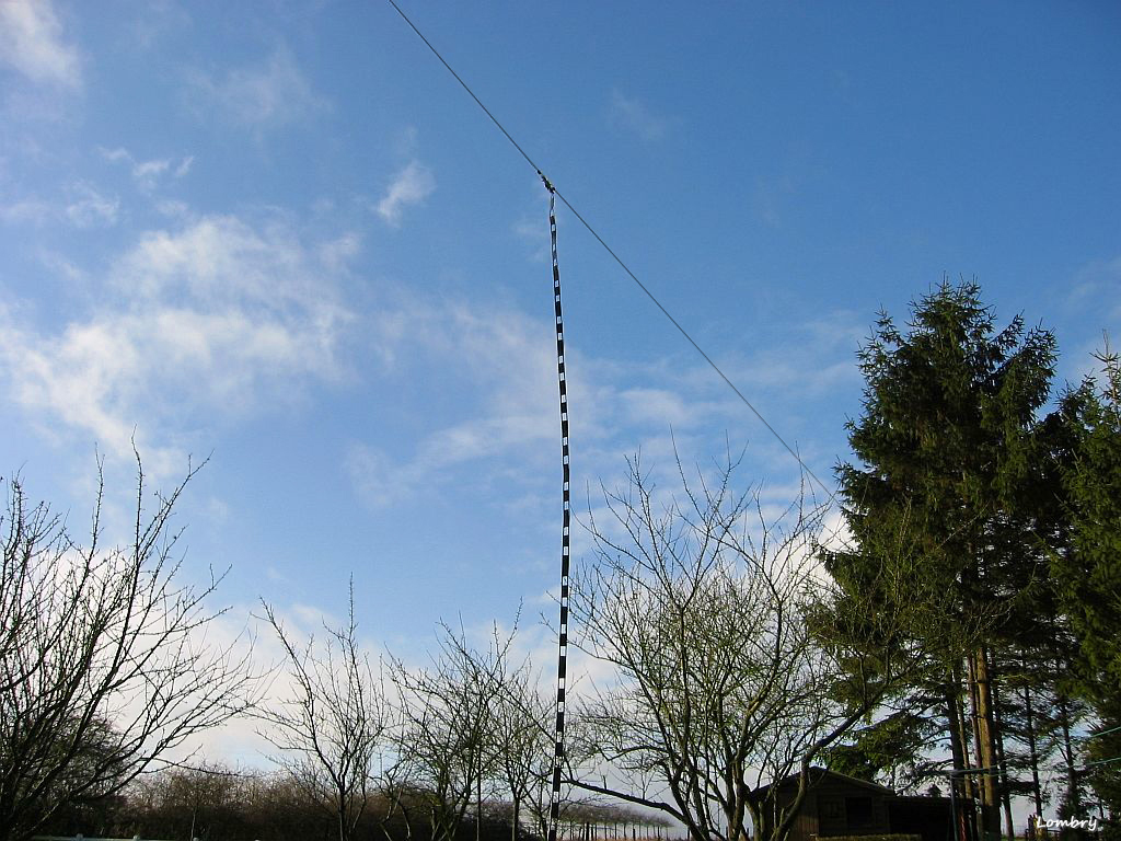
Line construction (III) Whatever the working frequency, on HF bands or V/UHF, there are two basic types of transmissions lines : the parallel-conductor also called "two-wire" or "open-wire" and coaxial, each model being divided in a variety of forms. Both types are divided in two main classes : - Cables in which the majority of insulation between conductors is air, with a minimum of solid dielectric mainly used for mechanical support. As we told previously it displays the lowest loss per unit length because there is power lost in dry air as long as the voltage between conductor is below the value at which corona forms. It displays also the highest characteristic impedance. - Cables in which the conductors are imbedded in and separated by a solid dielectric. Due to this design these cables show some power lost per unit length and display also a lower characteristic impedance. Air-insulated lines A typical air-insulated transmission line is the famous ladder line also called "open-wire" used to feed dipoles like G5RV (to not confuse with the air-insulated coaxials Aircom or Aircell). The two wires lines are separated by a fixed distance from 20 to 150 mm by means of insulating rods called spacers. They are usually made of insulating material such as phenolic or polystyrene. In HF the smallest spacers are used at the higher frequency (20 mm at 28 MHz) to minimize radiations. The feed line is usually made of ordinary #8 to #22 AWG conductors or tubing from 0.63-1.27 mm (0.25-0.5") diameter. In such sizes, using spacers from 20 mm to 250 mm, the impedance is ranging from about 200 to 800 Ω. As you understood the characteristic impedance depends of the distance separating conductors (b) and the radius of conductors (a) according to the next formula : Zo = 276 log (b/a) To this value you need to add the effect of the insulating spacers. Note that it does not matter whats units are used for a and b so long as they are the same units (e.g. mm or inches). For example, using a #16 AWG wire (inner Ø 1.31 mm) and 40 mm spacing from center to center (50 mm or 2" end-to-end) you will get a ladder line with a characteristic impedance of 523 Ω.
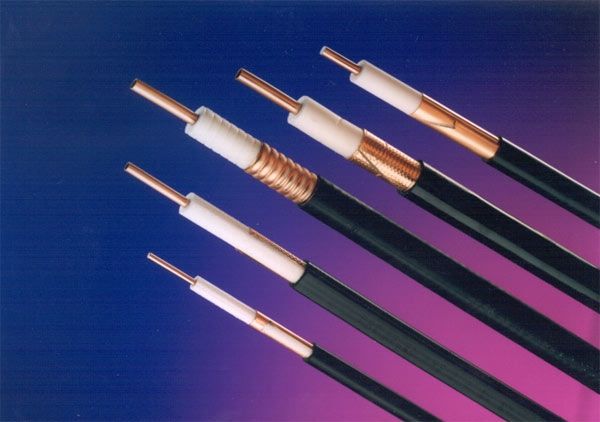
Because of the large spacing between conductors, it is harder to confine the field along with the wires (there is no solid dielectric to confine it) and a field of some intensity can exist in the surrounding air. Therefore this high impedance line is much more sensitive to weather effects than a low impedance Twin-Lead or coaxial line. Note that in some old constructions or for special applications a four-wire line is used. The spacers are of the same size than those used in two-wire lines excepting that they are made of insulating material in X-shape, the conductors being placed at the corners of the square. The impedance of this type of line is lower than the two-wire model, it is also better electrically balanced to objects that can be close to the line. Coaxial lines Coaxial cable is called "coaxial" because it includes one physical wire or channel that carries the signal surrounded (after a layer of insulation made of a solid dielectric) by another concentric physical braid, both running along the same axis. The external braid serves as a ground. One of the first commercialized coaxial was the famous RG-58/U that allowed to establish the first cross-continental transmission in 1940 by AT&T. This type of coaxial is not as protected against RFI as the RG-213 or Aircom often used by amateurs or the much thicker and expensive Belden RF-9913 used in very high frequencies. To read : Guide to Antenna Cables & Connectors, Telco Antennas
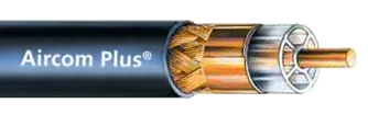
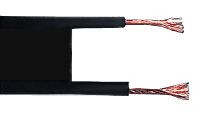
The fact that the insulation is made of a solid dielectric increases somewhat losses in the line, however such coaxials have lower loss at frequencies up to 100 MHz than any other line type because of the air emprisonned in the line can be kept dry. Currently the most performing coaxial cable is the Aircom+, a cable of 10.30 mm diamter with a loss of 0.215 dB/m at 2.4 GHz. It is better than Aircell which dielectric can absorb moisture and thus transform the duct in a true water pipe... The characteristic impedance of an air-insulated coaxial depends of the inside diameter of outer conductor (b) and the outside diameter of inner conductor (a) according to the next formula : Zo = 138 log (b/a) We immediately see that using same wire sizing as for the open-wire, the characteristic impedance of a coaxial line will be much lower. Typically a #16 AWG Ø 1.31 mm) or simplier the RG-58 has an impedance as low as 50 ohms, what perfectly matches the transceiver specifications without using any additional balun. More resistant, less bulky and easier to handle than air-insulated lines, the coaxial is today the type of feed line the most used by amateurs. Of course do not forget that is main drawback is to be not balanced to ground and other nearby objects. Twin-Lead lines Hybrid design between the air-insulated lines and the coaxial, Twin-Lead lines (which is in fact a trade name) are made of two conductors separated by a flexible dielectric from 10 to 20 mm wide often made of polyethylene insulation. Lighter, less bulky and usually easier to install than ladder lines, Twin-Lead lines are today available for both parallel-conductor and coaxial lines. There is however one drawback in using such lines, the fact that the power loss per unit length is greater than in air-insulated lines. Indeed when using high power with a high SWR the heat dissipates in the dielectric with consequence, in worst cases, to mechanically break down the line. White or translucid Twin-Lead looks however neater in appearance than open-wire lines. A typical Twin-Lead uses stranded conductors equivalent to a solid #12 AWG with a characteristic impedance of 75 Ω.
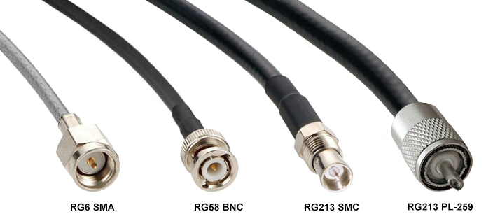
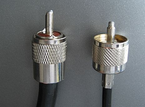
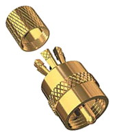
Coaxial fittings and connectors There is a wide variety of fittings and connectors designed to go with coaxial lines. The three main connectors are the PL-259, the BNC and the N fittings. PL-259 plug The famous "UHF" PL-259 plug and its complementary SO-239 chassis fitting are available for long time and are probably the type of connectors the most used by amateurs since the year 40's. They are however not weatherproof. They are available in two models, with or without UG-176/U or UG-175/U adapter (that is placed below the plug assembly). To assembly a PL-259 connector on a RG-213 or RG-58 coaxial line ends, slide first the coupling ring and optional adapter on the coaxial and let temporary the plug assembly (with the pin) aside. Trim then the vinyl jacket from the coaxial on about 20mm. Peel the coaxial braid, fan it slightly in order to fold it back over the coaxial such a way that it doesn't touch the central conductor. If the coaxial braid touchs the central copper you will get a short-circuit and the coaxial properties will be altered. In that case signals will never reach your RTX. If you use the adapter, slide it near the braid and press it down over the body of the adapter. Trim then the braid to about 10mm. Bare the central copper conductor on 10 mm. Screw the plug assembly that you let aside on the adapter or directly on the cable if you don't use it and solder the braid to the shell through the solder holes. Solder also the conductor to the contact sleeve. Be sure that the cable dielectric is not heated and swollen so as to prevent dielectric entering body. At last screw the coupling ring on the plug assembly. This connection is very easy to make and should looks like the PL plugs displayed below at right in their true size.
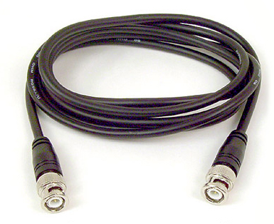
Once all parts are connected check your plug and ring with a multimeter and pull on the plug to test its resistance. If all is fine make your connections and switch on your RX. If you hear amateurs in QSO your antenna system is working properly. Otherwise if you receiver is silent, like disconnected from the antenna you have experimented a short circuit, more than probably in the way that you soldered your PL connectors. To avoid this problem, you can replace the classic PL-259 with a centerpin and solderless PL-259 CP-G connector. BNC connectors The BNC fittings (UG-88/U) are mainly used with small cables such as RG-58/U. They are interesting because they feature a bayonet-locking arrangment for quick connect and disconnect, and are weatherproof.
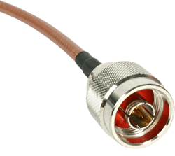
Its construction seems more complex because the BNC is constituted of 5 elements instead of 3 for the PL-259 but it is no more difficult. First trim 8mm of the RG-58 cable vinyl jacket. Fray the shield and strip the inner dielectric on 3 mm. This section will be in contact with the female contact of the BNC. Then tap the braid in order to slide the BNC elements. From the end, slide the nut, washer, gasket and clamp over the braid and let the female contact temporary aside. Insert the clamp so that its inner shoulder fits squarely against the end of the cable jacket. With the clamp in place, comb out the braid and fold it back on it. Trim about 2 mm from end. Then tin the center conductor and slip the female contact in place and solder it. If necessary remove the excess of solder. Here also be sure that the cable dielectric is not heated and swollen so as to prevent dielectric entering body. At last, take the body and push it into as far as it can go. Slide then the nut into the body and screw it into place with a wrench until tight. To end, hold the cable and shell rigidly and rotate the nut. Your BNC is assembled. "N" series fittings The last serie of fittings is the "N" series, N as Navy. It is designed to maintain constant impedance at cable joints. Harder to assembly than a BNC but the same way (except that you have to trim the first 14 mm of vinyl jacket), they are mainly used on 432 MHz band and higher frequencies. Last chapter Coupling the transceiver to the line
|
||||||||||||||||||||||||||||||||||||


