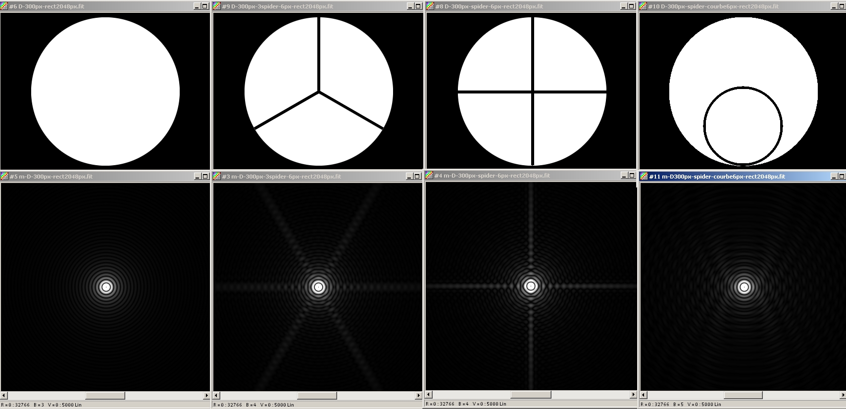
 Diffraction spreads the light in the direction orthogonal to the vanes. No spike is seen with the curved spider, the light beeing spread all around the star.
Effects of obstruction on the figure of diffraction
Sources :
Vladimir Sacek : http://www.telescope-optics.net
Suiter : http://home.digitalexp.com/~suiterhr/TM/Spiders.htm
No spider, 3 and 4-vane spiders, curved vane spider.
The thickness of the vane is the same for all spiders : 2% of the aperture diameter (but the mechanical stiffness would be quite different ...)
Log visualisation.
Diffraction spreads the light in the direction orthogonal to the vanes. No spike is seen with the curved spider, the light beeing spread all around the star.
The total amount of light inside the diffraction spikes is equal to the ratio between the front surface of the spikes and the aperture surface.
Thickness of the vane = 2% D |
Percentage of light in the spikes |
|---|---|
3-vane spider |
3.8% |
4-vane spider |
5.0% |
curved spider |
4.0% |
First ligne : no spider and 4-vane spider with 0.003 D thickness
Second ligne : 4-vane spider with 0.01 D and 0.02 D thickness
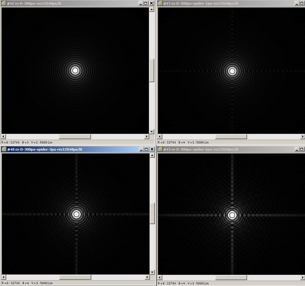
The amount of light diffracted in the spikes in proportional to the ratio between the front surface of the vane and the surface of the aperture.
Thickness of the vane (unit = D) |
Percentage of light in the spikes (no central obstruction) |
|---|---|
0.003 |
0.008% |
0.01 |
0.025% |
0.02 |
0.05% |
The Strehl ratio is reduced by the factor S' = (1 - 2 a) with a = relative front suface of the spider.
Thickness of the vane (unit = D) |
Percentage of light in the spikes (no central obstruction) |
Strehl ratio (no central obstruction) |
|---|---|---|
0.003 |
0.008% |
0.984 |
0.01 |
0.025% |
0.95 |
0.02 |
0.05% |
0.90 |
4-vane spider with increasing thickness : 0.003 D, 0.01 D, 0.02 D.
Left image: the minima of light in the spikes are outside the field of view. Middle image, one minimun can be seen on each side of the star. Right image, three minima can be seen on each side of the star.
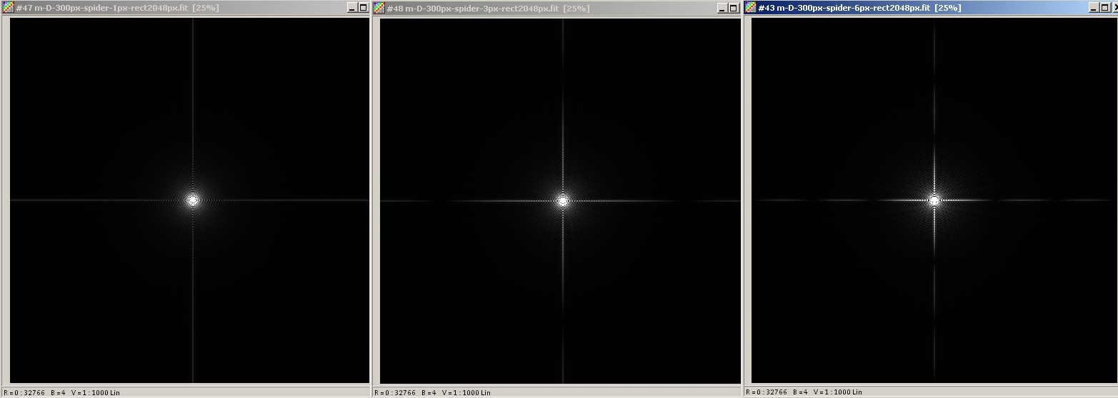
The width of the central lobe (= double of the distance between the maximum and the first minimum) is equal to 1/ relative thickness of the wane, in unit of Airy disk, with relative thickness = vane thickness / vane length.
Accordingly, a thiner vane will diffract less light, and additionally will diffract this light farther away from the star (or planet).
Thickness of the vane (unit = D) |
Width of the central lobe (unit = Airy disk) |
|---|---|
0.003 |
333 |
0.01 |
100 |
0.02 |
50 |
For example, with a 300 mm aperture (diameter of the Airy disk = 0.9 arcsec at 550 nm), we would have :
Thickness of the vane |
Width of the central lobe |
|---|---|
1 mm |
270 arcsec |
3 mm |
90 arscec |
6 mm |
45 arsec |
Accordingly, with a 6 mm thick vane, all the light of the first lobe (ie. 90% of the energy diffracted by the spider, ie. 0.9 * 5% = 4.5% of incident light) would fall on two segments 45 arcsec long (apparent diameter of Jupiter). Too bad for the contrast ...
22% central obstruction. 3-vane spider with increasing thickness : 0.003 D, 0.01 D, 0.02 D:
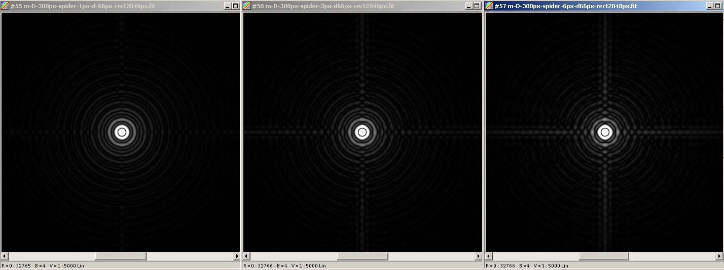
Because of the obstruction, the front surface of the spider is smaller, which results in less light diffracted in the spikes (compare with simulations without central obstruction).
Thickness of the vane (unit = aperture diameter) |
Percentage of light in the spikes (with 22% central obtruction) |
|---|---|
0.003 |
0.006% |
0.01 |
0.02% |
0.02 |
0.04% |
- The previous simulations are based on the actual mechnical thickness of the vanes.
- However, depending on the material and surface of the vanes, temperature gradient, ..., radiative cooling can create a boundary layer which increases the optical thickness of the vane.
David Vernet kindly provided us with a nice example with this Foucault-gram taken at the one-meter telescope of C2PU https://c2pu.oca.eu/spip.php?article11.
"The sky is up. The telecope is pointing 40° up. The cold boundary layer can be seen as a diffuse darker region above the four vanes, and also above the secondary miror cell. The vane are about 3 mm thick and painted in black. A closer look at the image shows that the boundary layer is thicker in the first 1/4 of the lenght of each vane. This is because the vanes are full height in their 1/4th length, while futher away there are carved with a large hollow (resulting in faster cooling)."
.
- The amount of light diffracted by the spider is proportional to the front surface of the vanes (surface of the secondary mirror excluded).
- The thiner the vanes the lesser light into the spikes, and the further away for the star or the planet the light is diffracted.
- The spider reduces the Strehl by the ratio S' = (1 - 2 a) with a = front suface of the spider (secondary mirror excluded) / aperture surface.
- To get the utmost performance, some care is to be given to the choice of material / surface properties of the spider in order to handle possible radiative cooling issues. Otherwise, the formation of boundary layers can occasionaly increase the optical thickness of the vanes beyond their actual mechanical thickness.
The previous images were calculated with Iris software using the formula : PSF = [ Module FFT (Aperture) ]^2
They are displayed in log visualisation.