A 254 mm telescope has been measured using the following setup :
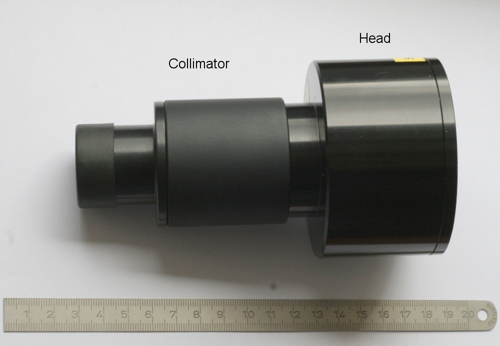
A natural magnitude 1 star, has been used. A 10 mm focal length collimator and Shack Hartmann presented thru these pages has been installed. Regarding the focal length 912.5mm (R=1825 mm) and F/D = 3.57, the pupil has a 3.57 mm diameter that does not fit perfectly to the 2.5 mm sensor height ! Nevertheless, measurments could be be achieved. Long averaging of spot deviations has to be carried out to avoid effects from turbulence.
The next diagram shows the reference spots (red) and the measured spots (white) and deviations amplified 100 times.

A quick analysis from this diagram shows the center of the mirror affected by a hole in the center and by a turned down edge.
The Zernikes coefficients (next table) are computed form the spot deviation.
Zernikes |
Meanning |
Zernike Coefficient (µm) |
Z3 |
Defocus |
-0.268 |
Z4 |
Astigmatism +/-45° |
-0.04 |
Z5 |
Astigmatism 0 - 90 ° |
0.032 |
Z6 |
Coma along x |
0.316 |
Z7 |
Coma along y |
-0.182 |
Z8 |
3rd order Spherical |
0.526 |
Z9 |
Trefoild, x axis |
0.11 |
Z10 |
Trefoild, y axis |
-0.073 |
Z11 |
5th order astigmatism +/-45° |
0.10 |
Z12 |
5th order astigmatism 0
- 90 ° |
-0.0085 |
Z13 |
Quatrefoild 1 |
-0.056 |
Z14 |
Quatrefoild 2 |
0.063 |
Z15 |
5th Order Trefoild along
x axis |
0.028 |
Z16 |
5th Order Trefoild along
y axis |
-0.008 |
Z17 |
5th Order Coma d along x
axis |
-0.062 |
Z18 |
5th Order Coma d along y axis |
-0.020 |
Z19 |
6th order Spherical |
-0.189 |
Some of the zernikes coefficient are not relevant, such as Z3, Z6 and Z7 because this is just showing geometrical mis-aligment of the mirror.
Other coefficient are negligible, meanning that the mirror is not affected by these defects : Z4,Z5,Z10,Z12,Z13,Z14,Z15,Z16,Z17 and Z18.
The table turns into :
Zernikes |
Meanning |
Zernike Coefficient (µm) |
Z3 |
Defocus |
0 |
Z4 |
Astigmatism +/-45° |
0 |
Z5 |
Astigmatism 0 - 90 ° |
0 |
Z6 |
Coma along x |
0 |
Z7 |
Coma along y |
0 |
Z8 |
3rd order Spherical |
0.526 |
Z9 |
Trefoild, x axis |
0.11 |
Z10 |
Trefoild, y axis |
0 |
Z11 |
5th order astigmatism +/-45° |
0.10 |
Z12 |
5th order astigmatism 0
- 90 ° |
0 |
Z13 |
Quatrefoild 1 |
0 |
Z14 |
Quatrefoild 2 |
0 |
Z15 |
5th Order Trefoild along
x axis |
0 |
Z16 |
5th Order Trefoild along
y axis |
0 |
Z17 |
5th Order Coma d along x
axis |
0 |
Z18 |
5th Order Coma d along y axis |
0 |
Z19 |
6th order Spherical |
-0.189 |
There is a large amount of Z8 and some Z19 : these are revolution defects.
Z9 : is not zero : may be the mirror is stressed by optomechanical setup ?
Z11 : has same value as Z9, more complex non symetrical effect is involved
here.
In that case, taking into account Z8,Z9,Z11 and Z19, the Peak to Valley wavefront error is 1.08µm, RMS is 0.28 µm so leading at Lambda=0.5µm a wavefront error of 2.16Lambda PV or Lambda/1.78 RMS.
Considering this is a small mirror, astigmatism is not so much relevant compared to Z8 and Z19 that represents revolution defects, so let's have a look to the revolution defects.
Remains Z8 and Z19 :
Zernikes |
Meanning |
Zernike Coefficient (µm) |
Z3 |
Defocus |
0 |
Z4 |
Astigmatism +/-45° |
0 |
Z5 |
Astigmatism 0 - 90 ° |
0 |
Z6 |
Coma along x |
0 |
Z7 |
Coma along y |
0 |
Z8 |
3rd order Spherical |
0.526 |
Z9 |
Trefoild, x axis |
0 |
Z10 |
Trefoild, y axis |
0 |
Z11 |
5th order astigmatism +/-45° |
0 |
Z12 |
5th order astigmatism 0
- 90 ° |
0 |
Z13 |
Quatrefoild 1 |
0 |
Z14 |
Quatrefoild 2 |
0 |
Z15 |
5th Order Trefoild along
x axis |
0 |
Z16 |
5th Order Trefoild along
y axis |
0 |
Z17 |
5th Order Coma d along x
axis |
0 |
Z18 |
5th Order Coma d along y axis |
0 |
Z19 |
6th order Spherical |
-0.189 |
In that case, taking into account ONLY Z8 and Z19, the Peak to Valley wavefront error is 1.00µm, RMS is 0.25µm so leading at Lambda=0.5µm a wavefront error of 2Lambda PV or Lambda/4 RMS.
The resulting image looks like this :

If the wavefront profile is plotted, the red bold curve can be acheived hereafter :
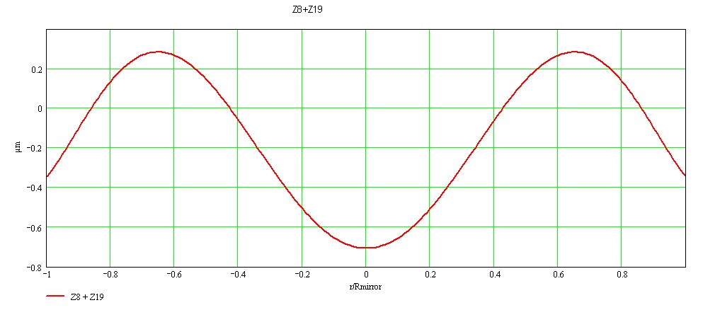
This shows as expected a hole in a center of the mirror, and turn down edges.
A metrologic device called aspherometer used in a big company has been used to compare the shack hartmann measurments. This is a good test to compare the SH with a calibrated and reliable device. I did not the test myself, it has been done by someone else, I was just a witness.
This device provides a glass surface error expressed in µm, compared to a wavefront there is a factor two, because the wavefront goes back and forth when touching a glass surface.
The following document is a test report issued from this device of the 254mm mirror and shows :
So the SH test matches perfectly the test achieved by this aspherometer !!

The two curves put together in the same plot shows a very good matching between the SH test and the Aspherometer.

| << PREVIOUS PAGE | NEXT PAGE >> |