|
|
|
From Longwire to Yagi
Yagi (IV) We sometimes hear amateurs telling that an antenna made of element shorter than a full wavelength do not perform well. It is a fact that reducing the size of elements by 50% does lower the efficiency by 1 or 2 dB. If the antenna is placed close to the ground, the loss is still higher. Thus for the purist nothing is worth working with full size elements placed l high... Right, but how to proceed in restricted places or when the structure is so huge than it becomes impossible to handle ? A half-wave dipole is very appreciated when it is associated to parasitic elements, a reflector and one or more directors, to design an array (beam). Indeed, in this configuration its advantages in directivity and gain overtake by far this small power loss. When such a directive array is erected well above the usual obstacles and common sources of RFI, it perform much better than any full length dipole. Let's take the time to review this true technological revolution. The gain offered by a simple half-wave dipole tight horizontally is about 2.14 dBi in free space (theoretic and thus never met in practice). To get more gain and directivity we can combine antenna elements, usually half-wave dipoles, into an array. These elements are either parallel (side-by-side, also called broadside) or collinear (end-to-end), fed horizontally or vertically depending on the desired polarization. The directional pattern and gain of a Yagi is determined by the relative amplitudes and phases of the current induced into all the parasitic elements. The power gain is directly proportional to the number of elements used at the condition to respect at best the next conditions : - The field of individual antennas must be in phase at the feeding point - The currents in all elements must be identical - The current induced in one element by other must be negligible (same radiation resistance). Among multielement aerials, the most familiar is the famous Yagi-Uda, name after the japanese engineers who invented its design in the '30s. This very common aerial that we usually call a beam (or Yagi for short, sorry Uda), is a version of the parasitic aerial array. It is applied to HF and upper frequencies, whatever the mode.
To understand how it works, in its basic form this is a simple half-wave dipole on which is added a single rod to form an H, the rod being spaced from the dipole by a small fraction of a wavelength (0.1-0.25l). By making the rod slightly longer than the dipole (driven element), it act as a reflector, modifying the response pattern to a cardioid (heart-shape) pattern, so it becomes directive. In practice the pattern is far to be perfect and there are always an unwanted rear lobe with some additional minor ones, more or less extended depending its selectivity. Adding a second rod slightly shorter than the dipole on the opposite side to the reflector, what is called a director, we reinforce and narrow the main lobe of the radiation pattern. Further directors may be added in front of the first, each slightly shorter (10-12%) that the previous. Each director slightly improves the gain of the aerial array, up to a limit of about 36 elements ! Beyond there is no significant signal increase. Adding parasitic elements reduces the impedance of the driven element, as seen by the feeder, and a folded dipole is frequently used to help to compensate for this.
The gain of a Yagi is thus directly depending on the length of elements and the number of directors. The gain is thus closely related to the antenna's directivity pattern. As we explained in the chapter dealing with basics of antennas, the angular width of the E-plane main lobe at the half power, or 3 dB points compared to the peak, represents the antenna beamwidth. It is about 60° for a 3-element HF beam and as narrow as 13° for a 6-element Yagi placed 1l over ground. 60° is large enough to work together Japanese and Korean stations from Europe without having to rotate the Yagi. A too narrow beamwidth is thus not necessary to work DX stations. A very narrow beam is mainly used on V/UHF where signals dissipate more quickly at shorter distance. At last, there is the question of alignement of elements. From time to time we see large beams which elements are slightly bent and we wonder how their owner can still work in such conditions. In fact, the nature of waves accomodates well of some twists in elements. Indeed, tests conducted in 2005 by Kent Britain, WA5VJB, with a UHF antenna show that a tilt of each element up to... 20° relative to the driven element does not provide any measurable effect on working conditions ! So don't worry if your elements show a little twist or are slightly bent; for dame nature it's the same. Advantages of a beam over a dipole If you have never worked with a beam but only with longwires, dipoles or verticals, I suggest you to sched an QSO-visu in the shack of an amateur using a HF beam (Yagi, quad or delta loop) and to use it for a while on the 20-m band. You will be more than surprised by its performances, even using a "small" 3 elements Yagi with traps.
First, contrary to most dipoles, this is a rotative system which receiving conditions change according to its bearing. But as we have just told, it is not always necessary to beam a station to work it. I explain. By design all beams display a rear lobe. You can take advantage of this so-called "loss" to work stations located at 180° of your bearing. If I take for example my own experience, I recently worked CT and EA stations although my beam was directed to HL and JA ! They arrived 59 in LX, as strong as some of my JA contacts. The gain difference between the front and rear side (Front-to-Back) of a beam depends on its design and usually exceeds 20 dB for a performing model. You can even work stations located at 90° of your bearing, where your gain drops subtantially (the F/S gain exceed easily 25 dB) : bearing to JA for example (35°) you can still work stations from the U.S.A.(310°). So, if you rotator fails, don't be too disappointed, you could continue to work almost as usual. I personnaly know an operator whose beam is locked for years in the same direction (fortunately close to USA-Europe direction). He continues to work DX stations almost as usual, as if nothing has happened ! Amazing ! Of course under the worst working conditions (strong QRN, pileups with strong QRM, etc) these are your patience and the performance of your receiver that will determine your success of failure in this matter. Last but not least, when you call "CQ DX" in SSB using a dipole or a vertical with 100 W of power, you are very happy when you work a station located over 8000 km away. This becomes a performance using a wire antenna of 20 or 30m long placed low over ground or a short vertical. If your beam is placed quite high over ground, it becomes as easy to reach a far DX that working local stations. From Europe, if you call "CQ South America" with a poor antenna system, you will quickly lost your voice to reach a few hams if not any; with a beam, even placed 5m high you will work tens of hams if working conditions are not too bad (100 W PEP, good propagation, few QRN and QRM). I remember the very first time that I used a beam. It was a 3-element placed 12m high (0.6l) in front of open fields. From LA to JA via ZS and QRP stations, it looked like all the world was standing behind the transceiver waiting for my call. Suddently it was like instead of making small skips between 2 and 5000 km using my vertical or the dipole, I did skips of 10000 km in once with the beam. A marvellous souvenir. When the propagation is in its best shape you can work the world or the farest entities hours long. Stacked Yagis Like all antennas, Yagis can be stacked either in broadside (side by side) or collinear (usually superposed) fashion to improve directivity and gain, and reduce as much as possible side lobes in which the energy is lost. The trick is to force the radiation pattern to concentrate in a specific direction instead of be radiated in the secondary and additional smaller lobes.
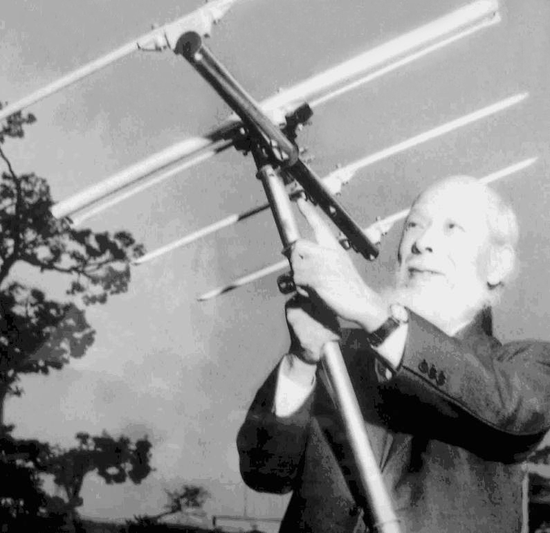
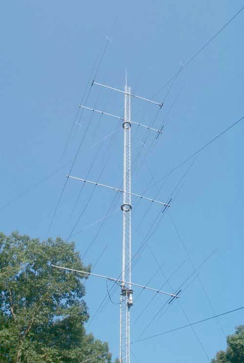
Installed broadside all antennas must be parallel and lie in a plane perpendicular to the axis of the individual antennas. It is the most common method, mainly in V/UHF. In collinear stacking all antennas are assumed to be collinear and all must lie in the same plane too. In both cases the driven elements must be fed in phase, using for example a feeder line in form of T and any type of matching section. Assuming that all antennas are of course identical, the increase in gain is determined by the spacing between the individual Yagis. As a result, we observe a decreasing of the beamwidth with a splitting of one or more side lobes. The number and amplitude of additional lobes depend on the shape and radiation pattern of the individual antennas, their number and spacing. The additional gain varies greatly since so many factors are involved and especially the height of the Yagis. You lost of course in the power due to the dividers or phasing hardenesses but it is by far compensated by the total gain of the stacked antenna system. From multiple experiments, it appears that the best gain occurs when the side lobes are approximatively 10 dB down. Stacking two antennas, we get this optimum value when the spacing is between 1l and 3l, where the half-power beamwidth decreases gradually from 60° to as narrow as 20°. Stacking 4 yagis gives some improvement. When spacing is less than 1/2l, stacking does not really improve the gain. It is also sometimes impossible to arrange when using full-size elements where the ends touch each another... Usually, in free space the gain of 2 and 4 stacked Yagis over a single one is between 3 and 5 dB. But it is much higher on long ionospheric paths. As the picture shows it very well, in HF two or more stacked Yagis made already a bulky and heavy installation that requires a large and sturdy pylon and much free space.
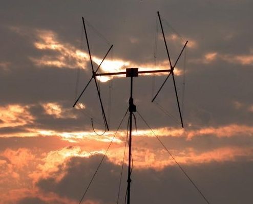
Due to the bulky and the weight of such installations, by design it is hard to work with stacked Yagis in HF. In these bands, for safety reasons the stacking of antennas requires an heavy duty tower (minimum 50 cm wide) equipped with a very resistant and large mast (at least 50 mm or 2" in diameter) and a rotator system sustaining a high wind load and torque. However, most amateurs working in HF with stacked Yagis gave up to ordinary rotator system to the benefit of a ring rotor. Some amateurs successfully stacked 2 over 2 over 2 beams, each an half wavelength apart to work on the 20-m band ! Others, like EA3JE, stacked 3 over 3 beams for the 15-meter band ! Such an installation usually weights over 100 kg (200 lbs.) and is placed on a larger tower 20 m high (100 ft) or more, bolten in a cemented base 60 cm to 1m wide and strongly maintained with a dozen of guy wires if not more... Therefore stacking four or even more antennas is much easier to accomplish on V/UHF or even on SHF where beams are very short and relatively light, able to support ten elements on a boom a few meters long. In practice these installations are mostly used for Meteor Scatter, Tropo Scatter, as well as for EME activities where high gain antennas are mandatory. Some EME enthusiastics have stacked up to 128-antenna elements ! The array is treated as if it were 4x 32-element collinears. The installation looks like a huge curtain of metallic trees erected towards the sky. It is without saying that such a big gun will give outstanding results. Quad and Delta loop Ordinary antenna arrays, aka beams, are constituted of approximately half-wave elements assembled horizontally over the ground. But we have seen about wire antennas that other forms can be used according to the same basic principles. One of them is the quad, a wire beam forming a vertical loop which perimeter is one wavelength long, thus radiating twice as much energy as a Yagi, usually cut at 1/2l. Invented by Moore, W9LZX, in the years 1940s, it is constituted of a driven element feeded as any other antenna array and a reflector ended with a stub, optionally completed with one or more dirtectors. The loop is 1/4l long on a side, sometimes a bit shortened.
Although it is vertically erected the polarization of a quad depends on the position of the feed point. When the driven element is fed at the base of a "diamond" loop or at the center of the horizontal side in a "square" loop, its polarization is horizontal like the one of a classic beam. When the feed point is on the side of the "diamond" loop or at the center of a vertical side in a "square" loop, the quad is vertically polarized. For HF bands the length of loop elements can be calculated using the next formula where f is the working frequency. Multiply these values by 3.3 to get the length in feet: - Driven element (m) = 305/f (MHz) - Reflector (m) = 313/f (MHz) - Director (m) = 296/f (MHz) - Element spacing = 0.14-0.25l (the smaller for antenna using more than 2 elements) Note that the Delta-loop is another variant of the antenna array such as the quad. It is usually installed the head below, like an inverted triangle, the base on top and parallel to the ground, with a perimeter one wavelength long. It is fed at the base (at the "top" of the triangle) to get an horizontal polarization. Easier to install than a quad but using less spreader arms, it is more fragile that the latter. Its performances are however similar to the ones of a quad. At last note that an hybrid antenna loop placed on its head (like a diamond), using for the lower part a vertical triangle and for the upper part an horizontal triangle is not considered as a quad but rather as a wire loop. It performs however as good as any quad or V-beam, all the more if the legs of the loop can reach 1l long as well as its height above ground. Log Periodic One of the disadvantages of a Yagi is its fairly narrow bandwidth. Where a broad range of frequencies is to be covered and there is no space for multiple aerial arrays, the log periodic aerial may be useful, though its gain is lower than the one of a Yagi. The name arises from the fact that there is a constant mathematical relationship in the length an positioning of each element, compared with its predecessor in the series. All elements, except the rearmost reflector, are driven, though not all are active at one time. A log periodic (LP for short) is frequency independent in that sense that the electrical properties of the antenna (characteristic impedance of the feed line, resistance, etc) vary periodically with the logarithm of the frequency. In fact to well understand how work a log periodic, all books dealing with this subject begin by inserting several mathematics formula and graphs in their chapter, a practice that we are not going to follow as my objective is not to show you how to design and build such an antenna but simplier to give you an overview of its functioning. To read: What directive antenna to select ?
How
it works ? For any signal within the bandwidth of the aerial, only
one element will be bear resonance. That element will act as a
dipole, the (longer) one behind it will behave as a reflector, and
the (shorter) ones in front of it as directors. The
feeder is connected at the front of the aerial, to the transmission
line formed by the twin parallel booms on which the elements are
mounted. As shown on the above graph, alternate half-elements are connected to opposite
boom, to
provide the necessary phase-change between successive elements. The length and spacing of successive elements reduces from the back by a factor n, less than 1. For a given bandwidth, a shorter array has fewer elements and a lower gain, and a lower value of n. Due to the difficulty to design and build them, their relatively low performances, their bulky and relatively high price, log periodics are not very appreciated by amateurs compared to Yagis or quads. You can however still find some in the garden of some active experimenters, in the one of amateurs who were charmed by their design or on the roof of some public buildings. Last chapter
|
|||||||||||||||||||||||||||||||||||||