New features
of version 4.32
(click here for download the version)
Version 4.32 - February 21, 2005
Support of RAW format of the DSLR Fuji S5500 (select the option FUJI (S5500) in the camera settings dialog box and PIC format (proprietary) in Setup dialog box).
Add the possibility to select the matching area for a batch stellar registration (see Deep-sky registration command of Processing menu). First, by using mouse, define a rectangular area in the first image of the sequence, then
This new possibility is useful if full frame matching fail. Important: If you choose this option, the only true efficient interpolation method is Linear, because Quadratic and Cubic produce high distorsion errors outside the selected area.
A bug is corrected in the LX200 paddle dialog box: The Align AD and RA values are now correctly interpreted.
The TRACK command is improved. If a date for the images is not valid the first column of DX.DAT and DY.DAT is the image index. The TRACK command produce also a new data file named STAT.DAT. The content of this file is column by column:
The image index
The X-shift relative
to the first image of the sequence
The Y-shift relative to the first image
of the sequence
The absolute X coordinate of the selected object
The absolute
Y coordinate of the selected object
The FWHM along X-axis
The FWHM
along Y-axis
The integral of the stellar PSF
The local sky-background
value
NEW COMMANDS
BINXY2 [IN] [OUT] [BINNING FACTOR] [NUMBER]
Bin a sequence of images.
SETNBSTAR [NUMBER]
Set the number of the brightest object used during the matching process of command like COREGISTER, full Deep-sky registration or astrometry. The default value is 30 objects, but some time it is necessary to increase this number (max value is 200) if the matching fail. If you run the command without argument, the actual default value is returned. The fixed value is conserved if you re-start the software.Improved support of the Meade DSI camera (management of the saturated pixels...). Support of RAW format of the DSLR Fuji FinePixS3Pro (select the option FUJI (FinePixS3Pro) in the camera settings dialog box).
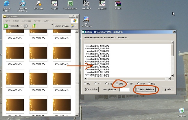
Creation of images lists
It is now possible to create a regular list of image (PIC or FITS output file, according to the choice makes in the dialog box "Settings" of File menu) starting from a batch of images having a non-homogeneous nomination. This possibility is extended to images sources with format JPEG, TIFF, PNG and BMP.
For example a sequence of images appearing in the disc with the names
DSC004.JPG
DSC009.JPG
DSC012.JPG
can be transformed easily into a sequence
IM1.PIC
IM2.PIC
IM3.PIC
who can be exploited by the batch functions of IRIS (ADD2, ADD_NORM, COREGISTER2,...).
Here the procedure :
1) Run the command "Select files..." from
"File" menu
2) Close or move the windows which are in front
of the selection dialog box
3) Select the type of source file (PIC,
FIT, TIFF, PNG...)
4) Drag and Drop since the Explorer browser the files of
your choice
5) Enter the generic name of the sequence to produce
6)
Click on the button Create the sequence
7) For come back to Iris principal
window, click the button Cancel.
For example:
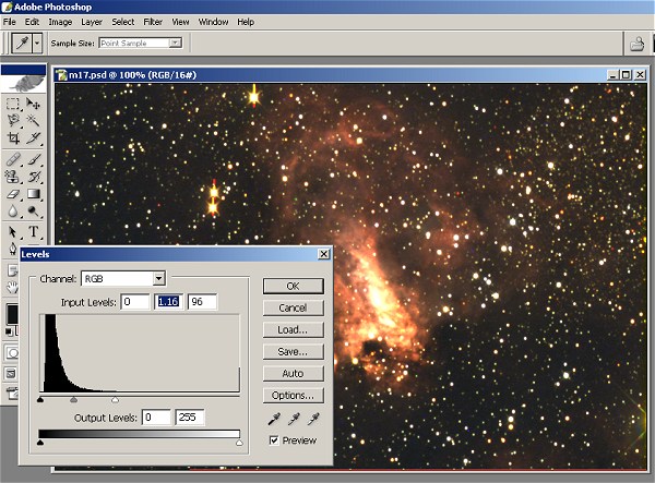
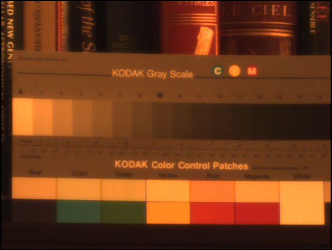
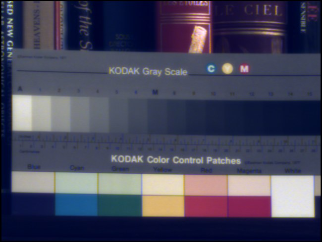
Export 48 bits images towards Adobe
Photoshop CS
IRIS supports in a native form the image processing on 16 bits depth, as well for images bw as for colors images. When IRIS exploits colors images, each pixels is coded on 3 X 16 bits = 48 bits.
It is possible to export your 48 bits images towards Photoshop CS software by using PSD link files (Photoshop Drawing - the Adobe bitmap). This procedure makes it possible to preserve all the richness of the images.
To export the image in memory in a PSD file it is necessary to use command SAVEPSD from the console. This command was improved in the version V4.31 to give an optimal result. For example:
SAVEPSD M17
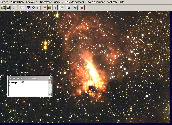
Note: the B&W images are exported in the same manner: IRIS duplicates in the three planes RGB the same 16 bits image.
Run Adobe Photoshop.
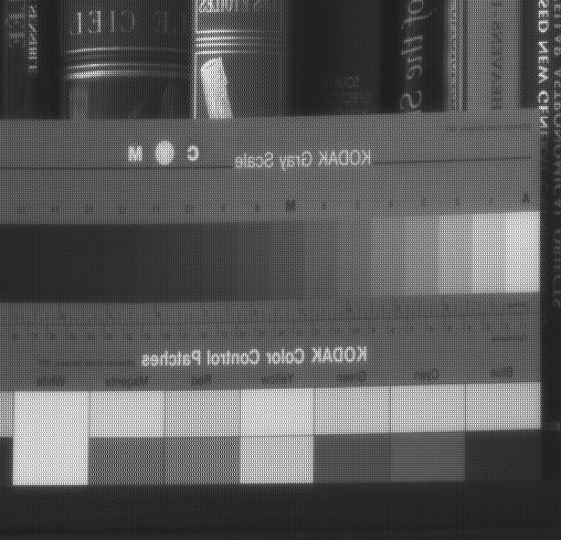
To open PSD file you should select File/Open from top menu:
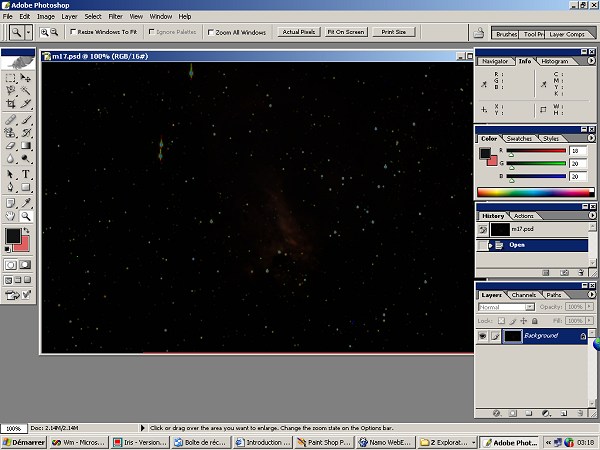
The image seem to be very darkness. Do not panic! The in-memory image is a real 48-bits depth document and it is easy to correct the aspect. For adjusts the contrast and the brightness of your images use Curves or Levels tools. For example, try to adjust levels by choosing Image/Adjust/Levels:
Registration
The version V4.31 includes an improved algorithm to find correspondences between two star lists (see details here). This type of algorithm is in the heart of astrometrics functions or command like COREGISTER (see the virtual equatorial application, further in this page). The old algorithm is however always available (useful in case of failure of the new). To commutate this last one in all the functions using the matching of star lists, make as a preliminary:
SETMATCH 2
For re-select the new algorithm (it is active automatically at the starting of the software), make:
SETMATCH 1
In addition, the choice of the degree of adjustment was
added in deep sky registration dialog box, accessible
since the "Processing" menu (command "Deep-Sky registration... ").
For example, filling the dialog box in the following way
is equivalent to typing into the console the two following commands
SETREGISTER 2
COREGISTER2 IN OUT 30
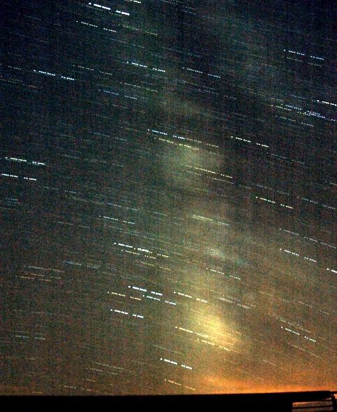
Here an application example. My observatory is not in completely ideal light-pollution situation !!!
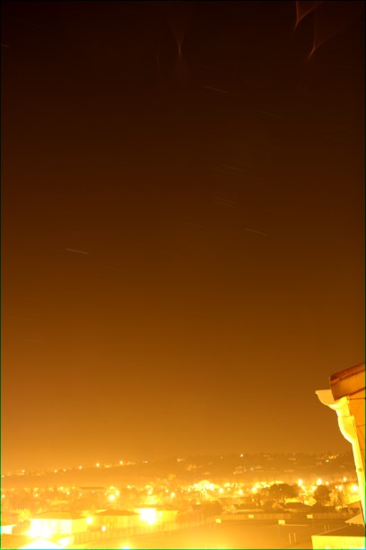
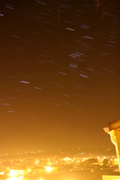
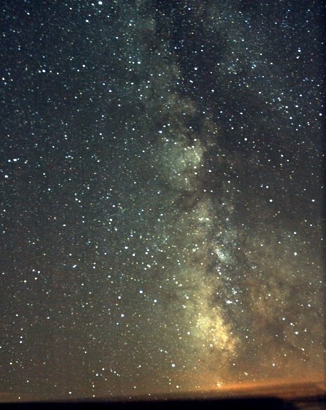
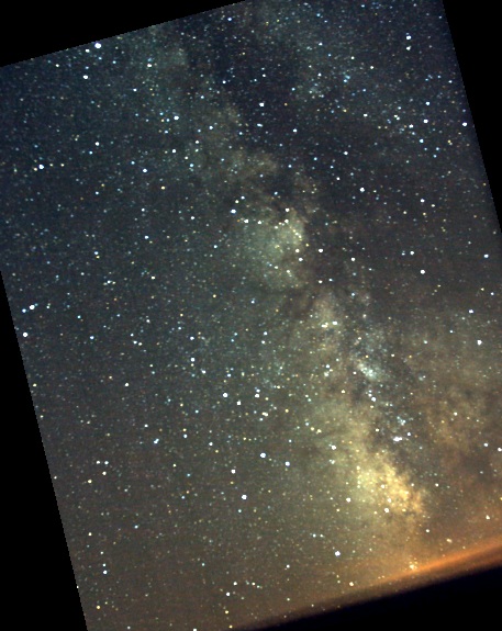
On left, the standard addition (ADD_NORM) of 30 images exposed each 20 seconds with a DSLR Canon EOS 20D equipped with a Canon lens zoom at the focal length of 17-mm. The equipment is attached simply to a tripod. Because of intense luminous pollution the star trails are hardly perceptible. On right-hand side, the stack of the images of the same sequence with command ADD_MAX2 improves largely the result (click here for some examples).
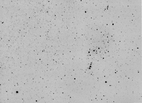
The result (negative view) of the stack of the 30 images after having superimposed them with COREGISTER2 by using cubic polynomial to correct optical distortion. It is a form of downtown deep sky astronomy without using an equatorial mount!
NEW COMMANDS
D_ALPHA [ ALPHA ] [INTENSITY]
Display a great right ascension circle in the in-memory image after an astrometrical reduction. [alpha] is the right ascension and [intensity] is the intensity of the drawing.
D_DELTA [ALPHA] [INTENSITY]
Display a declinaison circle in the in-memory image after an astrometrical reduction. [delta] is the declinaison angle and [intensity] is the intensity of the drawing.
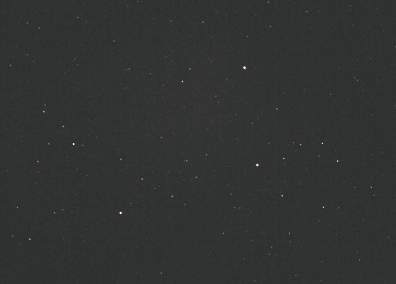
An application of these commands. Here an image of the head of Usa Major constellation realized with a EOS 20D and a Canon zoom lens used at the 40 mm focal length (20 seconds exposure @ ISO400). The image is downscaled to 25% of its original.
Fill the dialog box "Automatic astrometry..." of Analysis menu in the following way:

The catalogue SKY2000 is used considering the image is of wide-field type. The approximate equatorial co-ordinates of the center of images are provided (Alpha = 11h15m, Delta = +58°). The pixels size of EOS 20D detector is 6.4 microns, but taking into account the reduction factor of the image, their equivalent size is 4 X 6.4 = 25.6 microns = 0.0256 mm.
Click OK to carry out the automatic reduction. IRIS automatically finds the correspondence between stars present in the image and those of the catalogue.
At this stage the equatorial co-ordinates of an object in the image can be obtained by surrounding this one with a rectangle, then by typing COMPUTE command from the console or by run "Compute" command since the contextual menu. For more details on these operations click here.
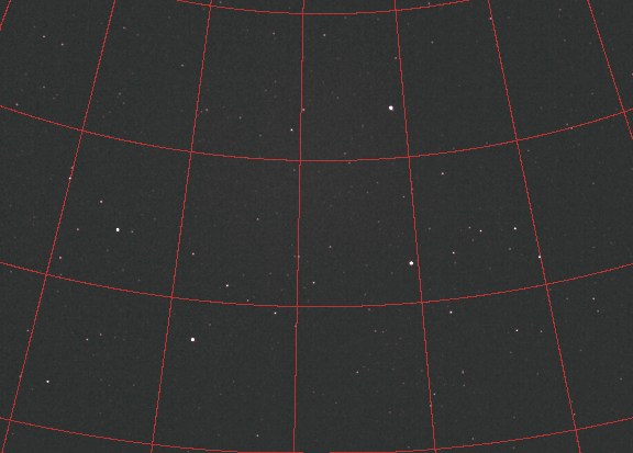
You can indicate an object in the image or trace a co-ordinates array with commands D_ALPHA and D_DELTA. For example
D_ALPHA 11H 600
D_ALPHA 11H30 600
D_ALPHA 12H
600
...
D_DELTA 50d 600
D_DELTA 55d 600
D_DELTA 60d
600
...
give
Support of format RAW of Nikon D2H digital camera (select the option Nikon (D2H) in
the Camera dialog box).
LOADDSI [ NAME ]
Load in memory a FITS image coming from the camera Meade Deep Sky Imager. LOADDSI converted YCMG matrix into an48-bits colors image corrects the ratio aspect induced by the rectangular pixels of the sensor ICX 404K which equips this camera (pixels of 9,6 microns X 7,5 microns). On the other hand the command does not correct the white balance, an operation which must be carried out specifically according to the context (see the command " RGB Balance... " of the Digital photo menu - typically the layers red, green and blue must be multiplied respectively by 0,53, 1,00 and 2,23).
A raw
FITS image of the camera Meade DSI (note the matrix of
pixels YCMG). Thanks to Jean-Paul Longchamp to have provided this
document.
The same image loaded and decoded with command LOADDSI.
The same image after white correction.
CONVERTDSI
Converted a raw image of the camera Meade DSI already in memory into an image color.
CONVERTDSI2 [ IN] [OUT] [NUMBER]
Converted a sequence of RAW image Meade DSI (generic name [in]) into a sequence of color 48-bits images (generic name [out]. The number of images in the sequence is [number]. The geometrical transformations are not carried out by this command.
LOG2 [IN] [OUT] [NORM] [NUMBER]
Calculate the logarithm of a sequence of images.
QR3 [NAME1] [NAME2] (or QREGISTER3 [NAME1] [NAME2])
Carry out the registration of stellar images [name1] and [name2] starting from a transformation of degree 2. It is pointed out that command QR applies a simple translation to superimpose the images (uses one star), whereas command QR2 applies an affine transformation (translation, rotation, scaling and use 3 stars). Cliquer here for examples about this functions. The interest of command QR3 is to take into account some distortion of the images. In counterpart, it is necessary to work with a greater number of stars, at least 6. For example, QR3 is adapted to register images carried out with photographic objectives lens with short focal length (see example below).
QR3 is adapted in the difficult cases of registration between images, when the geometrical transformation is not linear any more, and when the functions like COREGISTER fails (difficulties for automatically matching star lists).
The reference image is [name1] and Iris modifies the geometry of the image [ name2] for which superimposes on [name1].
The operation proceeds in two times. First, IRIS automatically load in memory the image [name1]. You have to click with the mouse (right button of the mouse) on stars regularly distributed in the image (at least 6 and up to 50). Choose bright stars, unsaturated and insulated if possible. Select the same stars in the second image, which is loaded also automatically. At the end of the selection calculation is carried out.
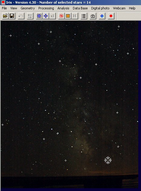
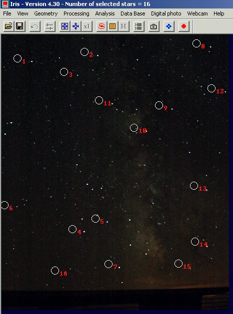
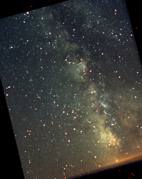
Here an example on a sequence of images obtained by Valerie Desnoux at the top of the Pic du Midi observatory ( September 2004). The instrumentation comprises a DSLR Nikon D70 equipped with a zoom used at the focal length of 18 mm (f/3,5). The unit is fixed on a simple photo tripod. No sideral drive is used. The exposure time for each image of the sequence is 30 seconds. The pointed area is the constellation of Sagittarius.
We want to register image named MV2 on image named MV1 (the latter is the reference in the sequence). Enter the command:
QR3 MV1 MV2.
IRIS displays image MV1 first (here reduced of a factor 0,25 on the two axes relative to original, but you can well on exploiting the full resolution). Selects about fifteen stars by making a click right after having positioned the cursor on their image (from this starting position of the cursor, IRIS compute a much more precise position of stars to a fraction of pixel ):
Once the number of stars selected is judged enough, one stops the selection process by a click on the STOP button STOP of the toolbar:
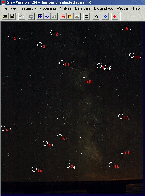
After a calculating time (precise measure of location of stars in image MV1), the software load image MV2 and invites you to select same stars. To help you in this spot the position of stars in image MV1 is indicated, as well the pointing order. It is imperative to follow this order of pointing in the second image:
The second phase of pointing can begin:
When all the stars were selected, IRIS compute the geometrical transformation automatically on the MV2 images:
Save this image:
SAVE R
add with the reference image to check the good course of the operation:
ADD MV1
Here the result:
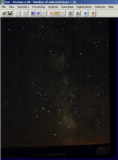
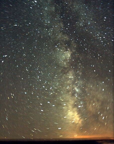
This principle is usable to add a great number of wide-field images carried out without equatorial mounting in order to lead to a consequent cumulated exposure time and a point-like result. The images are registered by couples and of course, the same reference image is used. Here the result for our example. First of all, a simple addition of 15 images of the sequence, which shows the traditional movement of the celestial sphere:
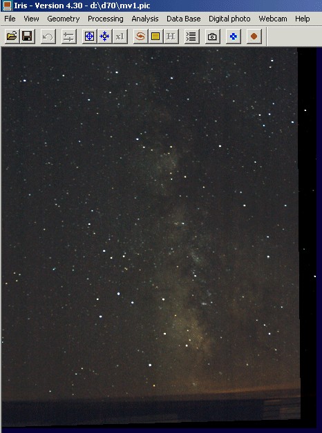
and after register the images of the sequence by using two methods:
On left, registration was carried out with only one star (commands REGISTER or QR for example). The rotation of the celestial sphere remains visible. On left, one used the new command QR3.
TIPS: in the situations where the shift between the images is not too significant and when brilliant stars are identifiable on the whole field image, quadratic registration can be carried out automatically. Here how to proceed:
A) fix quadratic registration with command SETREGISTER :
SETREGISTER 2
B) then, to carry out registration between the image A and the image B run the command COREGISTER :
COREGISTER A B
This command automatically finds common stars between the images and transforms the image B so that it is superimposed on the image A. For example, to process sequence I1, I2, I3, I4:
COREGISTER I1 I2
SAVE J2
COREGISTER I1
I3
SAVE J3
COREGISTER I1 I4
SAVE J4
LOAD I1
SAVE J1
ADD2 J
4
or more compactness:
COREGISTER2 I J 4
ADD2 J 4
For a full demonstration of these commands and virtual equatorial demo, click here.
Although it is possible to define higher degrees with
command SETREGISTER (the
default value is 1, i.e. linear transform), it is not recommended to use a degree larger than 2 with
command COREGISTER
because the interpolation can become defective when the stars do not constitute
a very regular grid.
AN APPLICATION OF QR3 COMMAND: ASTROMETRIC REDUCTION OF WIDE-FIELD IMAGES
It is possible with command QR3 to superimpose an image of the sky on a celestial map of the same area. So, it is for example possible to find the position of the objects by their equatorial co-ordinates. It is a rather teaching exercise making it possible to explain the equatorial system and the principle of projections in astronomy.
As an example we will merge on the wide-field image of Milky-Way (see the application of command QR3) a map image of the sky resulting from the SKY2000 catalogue (the support of this catalogue, complete until the magnitude 9, is a new feature of version 4.3). It is easy to find the SKY2000 on Internet, for example at this URL. You can also use the excellent software "Carte du Ciel" of Patrick Chevalley (www.astrosurf.com/astropc) who includes (and much more !) this catalogue. Let us suppose that the installation path on the disk of catalogue SKY2000 is D:\CARTE\CARTE\SKY2000. In the Setup dialog box (File menu) you must modify two fields in the following way:
Locate the approximate equatorial co-ordinates of the center of the field. For example here:
A precision of one degree is largely sufficient here.
Run the command " Display a sky map... " from the menu Data base and fill the fields in the following way:
The fields indicating the size of the produced map are filled automatically starting from dimension of the current image in memory. The size of the pixels of the Nikon D70 is 7.8 microns. The processed image having been reduced of a factor 4 following the two axes, the " apparent " dimension of the pixels is thus of 4 X 7.8 = 31.2 microns, or 0.0312 millimeters. The focal length of the optics used is 18 millimeters. Select option SKY2000. Finally give the limiting magnitude of the map. Here, one displays a limited number of stars in order to facilitate visibility, select magnitude 6. Click OK button.
IRIS automatically adds to the current image stars extracted the catalogues in form of red points:
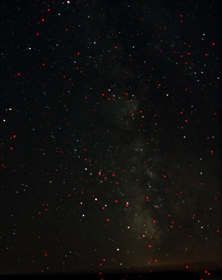
Note: for display only the map run the command FILL 0 before the dialog box limps i"Display a sky map...".
Back up this composite image. For example SAVE MAP.
Run command QR3 by giving the same name for the two arguments, here MAP:
QR3 MAP MAP
In the first phase of selection, click stars of the sky chart, in red. In the second phase of selection, click on corresponding stars of the deep-sky image. Example during the second phase:
Note: do not mistake corresponding stars! In certain situation, to facilitate the operation you can before applying command QR3 pre-orient the images by using commands like TRANS or ROT.
At this stage, the result is not that hoped since the transformed image contains at the same time the image of the sky and the map. That comes from the starting choice to indicate the same image for the arguments of QR3. Extremely fortunately the parameters of the transformation are preserved in a files on the disc (in the working directory) and it can be applied to any image with the assistance of command DEDISTOR (a new feature of version 4.3 of IRIS).
The parameters of the geometrical transformation are polynomials stored in files called POLX.POL and POLY.POL (a file by axis of co-ordinates). These files are at the heart of the astrometrical reduction functions of IRIS. Click here for details and tutorial.
Load the deep-sky image and transform this image into an equatorial system by running the command:
DEDISTOR POL
The argument of DEDISTOR command is the generic name of the polynomials files (we use here the default files POLX and POLY). Note: you can define your proper transformation equations and to apply them to any image with command DEDISTOR.
Here the result:
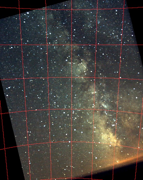
At this stage, you can again display the sky from the dialog box "Display a sky map...", without changing the parameters. The card is superimposed now correctly on the sky image:
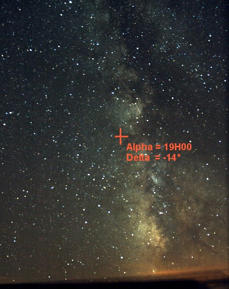
Reload the sky image and locate the position of the Messier 8 nebula (coordinate: Alpha = 18h04m and Delta = -24°20 ').
You can use for this commands DRAW_ALPHA and DRAW_DELTA which respectively trace a circle of coordinate in right ascension and declinaison. The parameters of these commands are:
DRAW_ALPHA [ ALPHA0] [DELTA0] [FOCAL LENGTH] [PIXEL
SIZE] [ALPHA] [INTENSITY]
DRAW_DELTA [ ALPHA0] [DELTA0] [FOCAL LENGTH] [PIXEL
SIZE] [DELTA] [INTENSITY]
[alpha0, delta0] are the approximate equatorial coordinates of the center of the field (the same used under display map dialog box). The focal length of the telescope and the size of the pixels of the sensor are provided in millimeters. The parameter [intensity] is the intensity of the circle of coordinated traced in the image. Finally (alpha, delta) are the coordinates of the drawn circle. In the example we will thus make:
DRAW_ALPHA 19h -14d 18 0.0312 18h04m
10000
DRAW_DELTA 19h -14d 18 0.0312 -24d20m 10000
for the following result

It is not well a great science, but this can help to illustrate some guiding principles in astronomy: the way in which an image is formed in the plan of the sensor, astrometry, etc. The transformation employed is known as gnomonic: the celestial sphere is projected on a tangent point with the sphere. This point is line of sight at the coordinate Alpha = 19h00 and Delta = -14°.
It is easy to display an equatorial grid in the image:
DRAW_ALPHA 19h -14d 18 0.0312 17h30m
10000
DRAW_ALPHA 19h -14d 18 0.0312 18h00m 10000
DRAW_ALPHA 19h -14d 18
0.0312 18h30m 10000
...
DRAW_DELTA 19h -14d 18 0.0312 10d
10000
DRAW_DELTA 19h -14d 18 0.0312 0d 10000
DRAW_DELTA 19h -14d 18 0.0312
-10d 10000
...
give this
General remark: whether the image was transformed geometrically or not, it is possible to make a complete astrometrical reduction starting from the command "Automatic astrometry..." (menu Analysis). However, in certain difficult situations, the registration carried out with QR3 can facilitate the automatic recognition between stars of the images and the catalogue. The astrometrical reduction from now on is facilitated wide-field images because the possibility of reading the Sky2000 catalog (300 000 stars until magnitude 9). Since version 4.3 the astrometrical reduction is compatible with the images 48 bits (but calculation is made on the green component, which generally has the best signal signal to noise ratio). Here how to fill the astrometry dialog box in our example:
With the end of calculation the stars suitable for the astrometrical reduction are surrounded by a circle:
The parameters of the reduction are also turned over (200 common stars between the image and the map were used for the reduction):
L1=732 stars, L2=856 stars, COM=200
stars
No-rejection
+9.97880e-001 +2.48090e-001 -8.17251e+001
-2.51256e-001 +9.9683ë-001 +6.42318e+001
Error Ra=109.44 " - Error
Dec=102.46 "
Magnitude constant=14.731
You can now use commands like COMPUTE to find the co-ordinates and the magnitude of an object in the image. Cliquer here for more details.
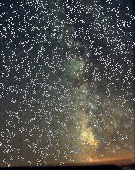
GOOD USE OF FUNCTIONS FOR FLATNESS THE SKY BACKGROUND
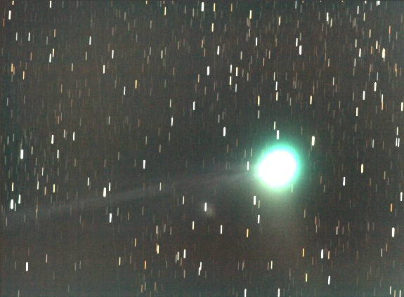
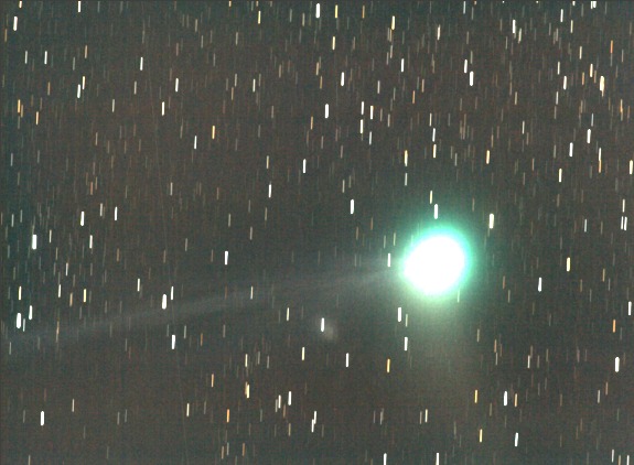
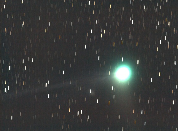
Analyze the image below of comet C/2004 Q2 (Machholz) obtained on January 11, 2005 with a camera Canon EOS 20D and a telephoto lens Canon of 400 mm at f/5.6:
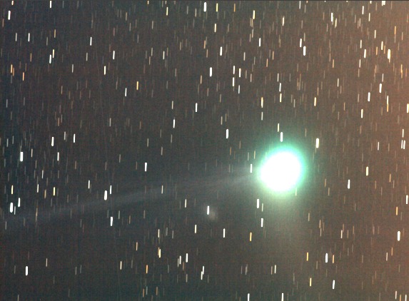
This stack of 18 frames exposed each 2 minutes clearly shows a problem in the content of sky. This one is far from being uniform. However the preprocessing was carried out correctly, in particular the flat-field correction was very effective to remove he shades of dust. But a gradient remains visible in the image. The reason is that this image was taken under very critical conditions, since an observatory greatly polluted by the urban lighting. The sky itself does not have a uniform intensity and parasitic reflections disturb the image. For a view of the observatory and other results concerning the Machholz comet, go here.
IRIS has tools for uniformise the sky background. Command SUBSKY is very practical for that. Let us apply there for this image. Enter simply the command SUBSKY in the console (no parameters):
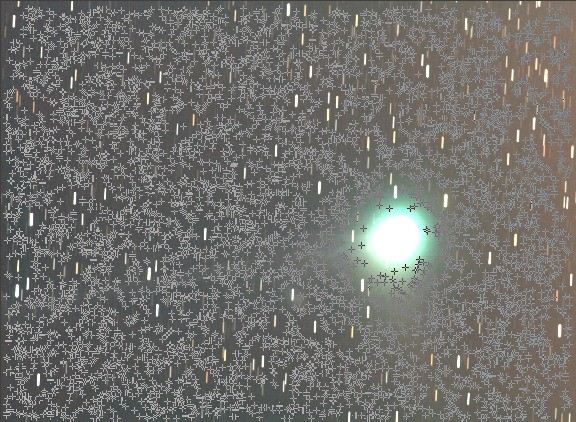
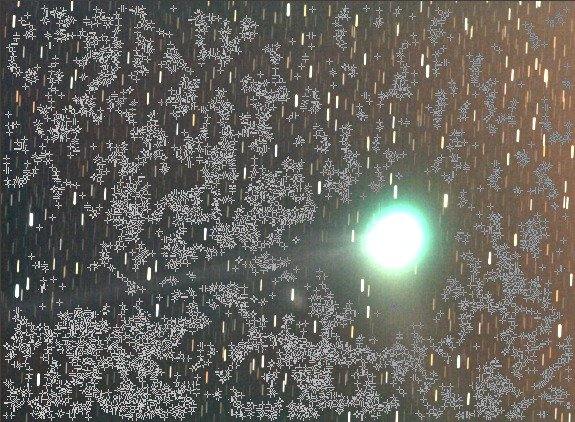
IRIS selected randomly points in the image while trying to avoid the objects which is there (the point position is indicated by crosses). Unfortunately many points are include the comet coma, not only the sky background.
While acting on the thresholds of visualization, the starting image is replaced by the processed image. The progress is significant, but as one could expect it, the adjustment of the sky background is not excellent, in particular around the coma, which is critical (aureole effect).
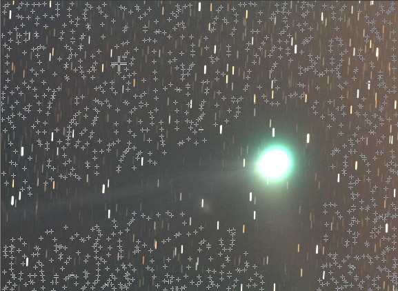
IRIS makes it possible to adjust the operation of command SUBSKY through command SETSUBSKY. This last ha two parameters: the selection point sensitivity (Sigma paarameter) and the degree of the adjusted polynomial (Degree parameter). Default values are Sigma = 4.0 and Degré=3 (if you run command SETSUBSKY without parameter, these parameters are returned to you). To prevent that the software points in the comet image it is necessary to increase sensibility detection of SUBSKY command. Try Sigma=0.8:
SETSUBSKY 0.8 3
or from the dialog boxialogue " Background fit... " of Processing menu:
Load the image to process and run the command SUBSKY (or click on OK in the dialog box above):
Now the coma is more preserved, but problems remain visible in faint extensions and on the plasma tail.
The result on the image, above, is however much more satisfactory, quasi useable just as it is. But it is possible to still make better by carrying out the pointings with "hand", via commands POINTON and POINTOFF. It is well longer job, but all the parameters are now controlled. A significant innovation in IRIS V4.3 is that the operation of pointing and adjustment functions act directly on 48 bits colors (remember, use the proprietary PIC format for the images, not the FITS the format).
Reload the image to be processed, then type command POINTON (it does not have a parameter). The mouse pointer changes when it passes on the image. To carry out pointings make right click. Avoid stars and comet. You can enter up to 3500 manual pointings in IRIS V4.3!
Here the result of the manual pointing. When the points are considered distributed uniformly and in a sufficient number, you can synthesize an artificial sky background. But before you must indicate to the software the adjustment degree of the polynom with command POLY. For example for degree 3, generally a good choice:
POLY 3
During the execution of the preceding command, IRIS compute the polynomial which fit the selected point (at least square sense). Nothing is apparent on the screen. To calculate the synthetic sky it is necessary to run command SYNTHE (it does not have parameters):
SYNTHE
Here the result:

Save this background image in a temporary file (here SKY):
SAVE SKY
Reload the image to be processed (named COMET for example) and subtract the artificial (we also add a constant of 500 to all the pixels for facilitate the visualization of the weak parts of the image):
LOAD COMET
SUB SKY 500
And here the result of our efforts:
The bottom of sky is now very uniform, exactly as if the image had been acquired with a dark sky.
To leave the pointing mode, type command POINTOFF.
For better appreciate the quality of correction of the sky background, here two images before and after the processing with a very high contrast and negative display (the images as a preliminary were converted into black and white with the function " 48 bits to 16 bits "of numerical Digital photo menu):
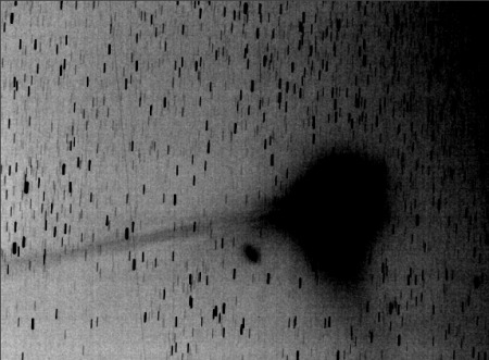
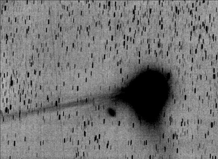
Left, before
the correction of the sky background. Right, after correction. The flattening of sky has well on an aesthetic interest,
but it is also significant to carry out precise photometric measurements. The
spot on the left of the coma is the diffuse nebula NGC1333 (see here).
|
|
