|
|
|
Assembling your antenna system
Constructing of the tower base (III) First, do you respect the regulation ? For security reasons, like any object erected in height near housings, to avoid that the tower falls on someone or on the housings by high winds, even if it is bolten in a deep concrete base (its top can break), you must legally secure your tower in placing it at a distance of at least 1.5 times its height from any infrastructure In taking a 10m high tower, the legal distance is 15m from housings and 2m away from the neighbour's property, so you need a free space of 34x34m (112x112') or about 11 ares. We will say to you have it. To last years outdoor any tower has be supported by a sturdy concrete base respecting if not the professional specifications, often too expensive, at least some construction and security standards. First, for the heaviest or highest installations do not hesitate to request the help of the manufacturer for advice or contact a civil engineering company used to work with such loads. Assembling a tower requests skills and a serious planning. If this is your first construction, that it is to support a 2-element quad or a bigger gun, it should be interesting that you visit some near building sites to see how they start work on the concrete base or how they construct a big pillar for example. Read also the ham magazines that regularly publish the works of the best handymen as well as books devoted to antennas published by ARRL or RSGB for example that usually reserve several pages to masts and supports (ARRL Handbook, RSGB Antenna File, etc). You could also find these publications in large libraries. If you purchase a new tower, the manufacturer will provide you detailed instructions for properly constructing the base and assembling the tower. If you have no plan, you can always "copy" the instructions of any other tower or the ones found in magazines, and if necessary slightly modify the dimensions to your needs, what most amateurs probably do. The foundations Any builder used to work with concrete and steel should tell you that a tower should be erected over a concrete base reinforced with a steel-bar framework on which the feet or the tower base assembly will be boltened. This is the classic way of installing a tower safely. The concrete base is driven in a hole from 0.5-1.5m depth (20-60"), depending the weight, the length and the design of your tower. This hole is 20% larger than your tower in order to insert without problem the steel framework just in the middle of the space. The hole must be large enough so that the anchorage system can be partly sunk in the concrete. Place at the bottom of the hole a few big rocks to support the framework. To keep the liquid concrete in position, a wood form made of fir wood boards 5 cm thick (2") is constructed around the top of the hole. If the soil is poroux, crumbly like sand or too soft, the concrete might flows into the ground. In this case densify your concrete and drive a hole twice as large.
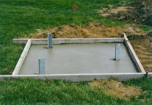
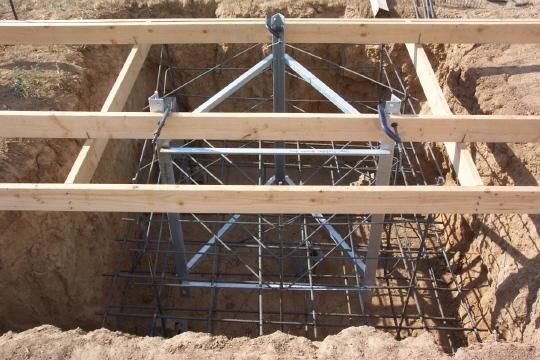
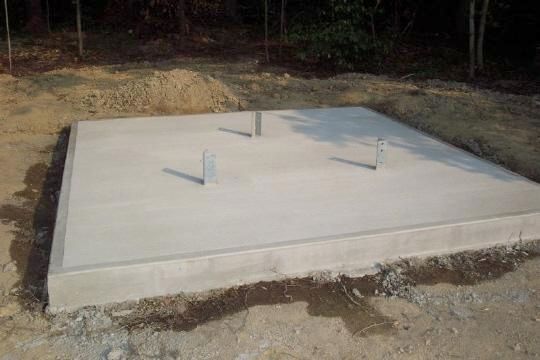
Then construct the steel framework and prepare the anchors (hence the interest to visit a building site). The framework is made of four No.6 RE-bar as long as your hole but shorter, that will be placed vertically near the corners of the hole. All ends should be bent to the inside. This frame is consolidated and bond to horizontal loops made of No.4 RE-bars wired to the vertical rungs each 50 cm (20"). So you need only 3 steel hoops on all the lenght of the framework. After building check all dimensions and that all segments are well perpendicular to each another. It is not mandatory to level the steel framework as it will be sunk in concrete but try to prevent any potential problem. Although we will review this issue when we 'll speak about lightning protection, in order to minimize the potential of a spark jumping from the bonded RE-bar directly to the earth, there needs to be a minimum of 10 cm (4") of concrete between any metal element and the earth (like the floor and the walls of your hole). The anchors are specially built to fit your tower mounting base. Either the feet of your tower provide the necessary holes on all their length to screw bolts and nuts or the manufacturer provided a base assembly. This base shows four or more holes used to bolt the anchorage system, hence the necessity that this last is thread. If you must made the anchorage system yourself, anchors have to be made of stainless steel, 40 cm long (16"), sunk at approximatively 3/4th of their length in the concrete. They must stand out of the concrete to bolt the base assembly. The optional thread will be adapted to your nuts. But do not work for nothing as, as we just told, the anchorage system, bolds and nuts are usually provided by the tower manufacturer. When all tubular elements are welded and assembled, insert the steel framework in the hole, well vertically, and just after put the anchorage system in the middle. Bind it to the RE-bar to create a ground system, called in this case an Ufer ground. Check immediately that all is properly set with the level and the ruler. In case of mistake do immediately the adjustment. The concrete base From the proper installation of the anchorage system will depend on the sturdiness and plumb (verticallity) of your tower. However it is very hard to see a misalignment of the anchorage system with the tower feet or with the mouting base or, worst, a lack of plumb at ground level. To prevent this type of problem, if your tower base is not too high I suggest you to bolt on the anchorage system the first section of the tower mounting base. That will ensure you that all is properly set once sunk in the concrete. Indeed, in this way it will be much easier to check the plumb on a long panel or a rung of the mounting base, and make if necessary the small adjustments before the concrete hardens. In anticipation of these small adjustments, prepare aside a wood board, a wood saw, a hammer, nails, a tape, a level, a ruler and a pencil. In case of trouble these accessories will help you to quicky made a spacer for example, to adjust the alignment of the anchorage system. Then, as your concrete base will have to emerge at bit over the ground and that the concrete will stay liquid for sometimes after pouring, construct a wood square form around the hole of approximatively 10 cm high (4"). Place a transversal board on top that will be put down on the wood form. It will serve to temporary attach the anchorage system to prevent it to sink in the concrete during pouring and until it hardens.
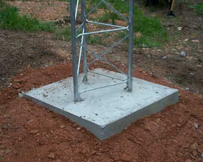
Now it is time to prepare your concrete. Don't work too fast, the concrete is very heavy, and it splashes ! Now go quickly but conscientiously. When all is ready, that the steel RE-bars and the anchorage are in position, each well bond to the other, that your wood form is firmly attached around the hole and the anchorage well attached to the wood board, pour the concrete over the foundations up to the top of your wood form (thus 10 cm or 4" over the ground). Level the top and check it is well horizontal. This is mandatory if the first tower section is welded to an horizontal plate like in the picture displayed above (below left corner). If you cannot drive in the ground over 30 cm depth, what is common in hill areas and ranges, or if you want lighter foundations to support a small antenna (< 20 kg, 40 lbs.), you can prepare a small hole 50x50 cm aside and 30 cm depth only (20x20x12"), place the feet of the tower inside and pouring the hole with concrete. Of course in this case your antenna must be guy-wired. Such small foundations are perfectly able to support a small beam (up to 20 kg) for years under wind gusts over 100 km/h (60 mph). It cannot resist long times to winds blowing over 120 km/h (75mph) on heavy or very long Yagis. In this case, to increase the security of this small installation I suggest you to sink in the foundation a small wire netting, without to forget the maintain the tower with guy wires, but we will see that later. In all cases check with accuracy the level and plumb of your base and anchorage system. If you don't do it now, when the concrete will be hard you will need of a pneumatic drill... Your concrete base is now achieved and tomorrow you might assembly your tower and the antenna, lucky you are !
A word of caution about Ufer ground To prevent you creating a specific external grounding system to protect your ham shack against lightning strikes, and if you have not started yet the construction on your tower, you should take advantage of the tower's connection with the earth as part of your external ground or Ufer ground. But be aware that if the Ufer ground is improperly constructed you do run the risk of exploding portions of the concrete ! This is to prevent such an accident that it is required that the pieces of RE-bars that constitute the framework be electrically connected to each other, whatever can write some radio amateur handbook on this subject. In your example this was accomplished by welding them to the horizontal steel loops. In addition, the anchor bolts must also be electrically connected to the RE-bars. This is a bit more difficult to accomplish since many manufacturers do not permit them to be welded due to the possibility of changing their mechanical strength. A simple mechanical clamp will work. As we told, in addition there must be at least 10 cm (4") of concrete left between the framework and the surrounding earth.
But for what reason the concrete could explode ? Tower base concrete explosion is caused by an arc that takes place within the concrete between two pieces of metal that are not electrically connected to each other. Since the concrete almost always has moisture, the heat of the spark caused by a lightning strike expands the moisture and weakens or destroys the concrete. By bonding the metallic elements of the tower base together, you achieve two things : no potential for a spark within the concrete and you create a Ufer ground. A strap emerging off the concrete can then be use to ground your ham shack as we will see in the pages dealing with the lightning protection. Next chapter
|
||||||||||||||||||||||||||||||||||||