Antilhue - Chile

![]()
![]()
![]()
![]()
![]()
![]()
![]()
![]()
Antilhue - Chile
|
|
The advent of large chip CCD cameras for amateur use has put more requirements on the optical quality of the imaging systems. Even though refractors offer generally a much better corrected field than other optical systems, field curvature on non-Petzval systems will be noticeable in the corners of a 36mm x 24mm chip, such as the one used in the SBIG STL-11000 camera. To counter these effects, TEC (Telescope Engineering Company) now offers a dedicated Field Flattener (FF), consisting of a 2 lens optical assembly in a black anodized aluminum screw-in cell. This document discusses the findings of the field flattener FF200 that was designed specifically for the model APO200FL, a 200mm (8 inch) oiled triplet f/8 apochromatic refractor. According to Yuri Petrunin at TEC, these are the theoretical
spot sizes calculated for the APO200FL refractor and FF200: It was also pointed out that for the given simple two lens FF design some aberrations in the center are introduced in order to correct the edges. By adding 1-2 more lenses one could achieve slightly better overall values, but cost would rise prohibitively. As can be seen from the figures above, spot sizes are nearly identical from the center (15 microns) to the very edge (18 microns). It is worth noting that these values are polychromatic (i.e. for all colors combined), and are substantially lower when using filters. Then, spot sizes will be near 10 microns for each color, which is very close to the theoretical limit of the given focal ratio. This, of course, implies re-focusing for each filter, which is common practice anyway. The FF200 field flattener screws directly to the large drawtube of the APO200FL's 3.5" Feathertouch focuser. The camera side is equipped with a Pentax 67 outer bayonet and compression ring. Thus, a Pentax 67 camera can be coupled directly to the FF200 and the film plane will be at the 86.4 mm metalback design distance. When using a CCD camera, one or more adapter(s) must be inserted to put the chip at the same distance. For this test, I used off the shelf parts made by Astro-Physics, part numbers A1261 (adapter) and A3503 (0.75" thread-on extension ring) between the FF200 and the STL-11000 (equipped with the RCOS STL-2-AP adapter )
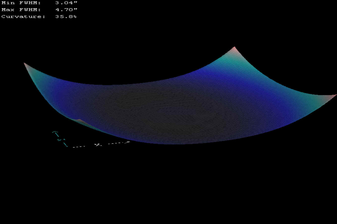
Before - after evaluation Rather than rely only on a purely visual before-after assessment of star shapes and sizes, I used the very useful software application CCDInspector (from www.ccdware.com ). This software not only helps in precisely collimating your telescope, grading your frames according to FWHM, etc, it also has a very useful field curvature tool. Below is the result screen of a calibrated single unfiltered 2 minute exposure taken of Eta Carina under average seeing (5/10) on March 4th 2006. The scope is in perfect collimation and there is no tilt of the image plane (CCD chip surface). Note the variation of FWHM from 3.04 arc seconds in the center to 4.70 arc seconds in the corners. Field curvature reads 35.8 %.
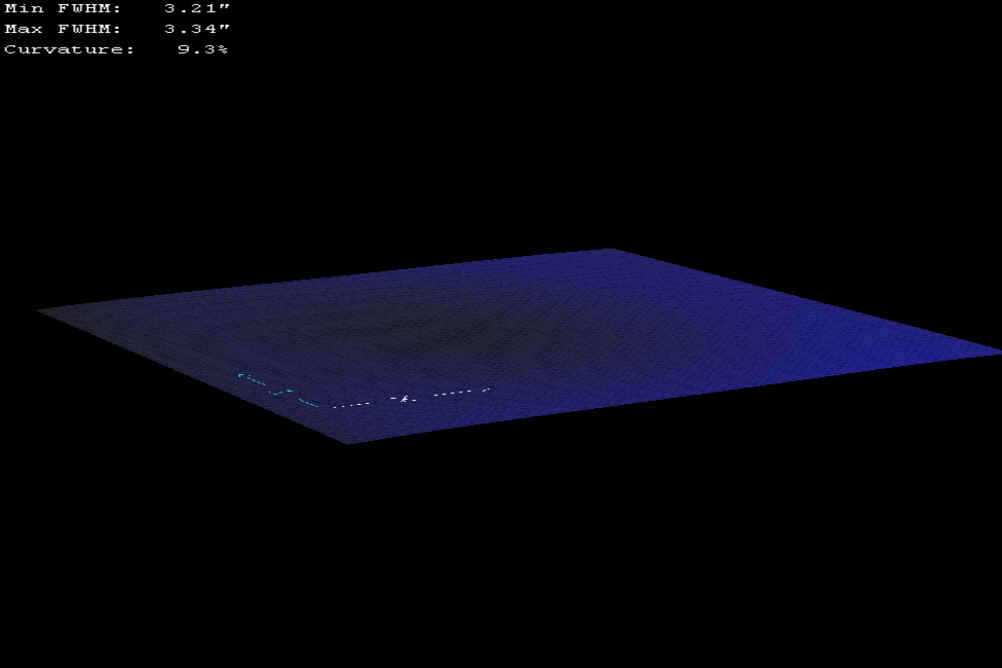
And here is the graph of a calibrated 13 minute exposure of M 16, taken under similar 5/10 seeing conditions on August 23rd 2006 with the FF200 installed. There is only 0.13 arc seconds variation in FWHM over the whole field (3.21" to 3.34") and the curvature figure has come down to a very good 9.3 % !
When looking at CCDInspector's "3-D Viewer map" the improvement becomes even clearer:
BEFORE:
AFTER:
Manual FWHM measurements in MaxImDL/CCD confirm the above system evaluation. Visually, the quality of the star images in the corners is undistinguishable from that of stars in the center. Also, I could not detect any chromatic or other effect after the FFC was put in the imaging path. The jury is still out on the effect of the FF200 on star image quality (PSF): one night's testing is not sufficient to evaluate if the excellent tightness of the stars in straight through mode is maintained after the 200FF is introduced. Conclusion: The above comparison shows that the TEC FF200 does an admirable job on flattening the SBIG STL-11000's field. The APO200FL is now well equipped to face the next generation(s) of even larger CCD chips. Finally, here is the final result of the M 16 image. <end>
|