|
|
|
The radio propagation
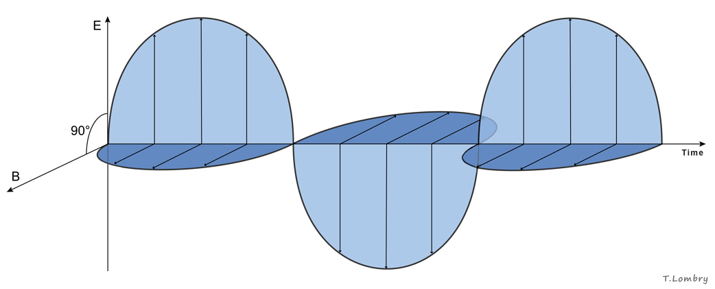
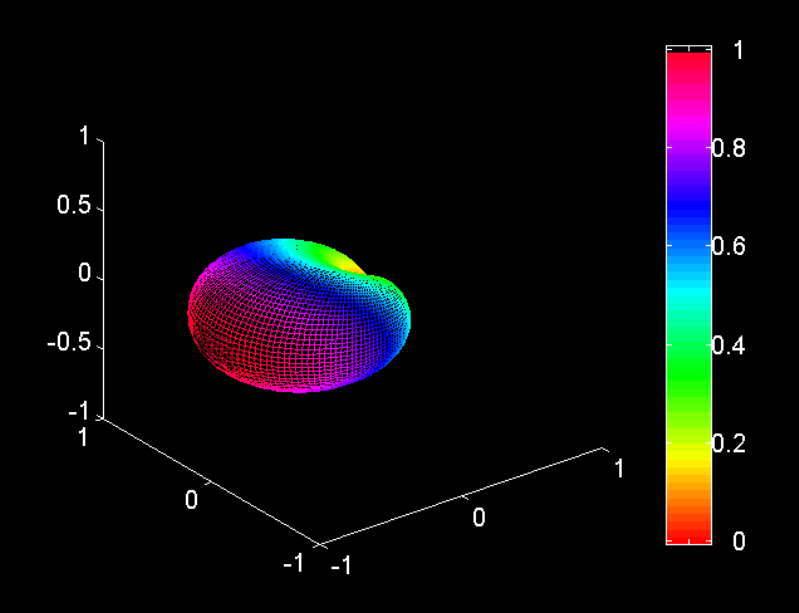
A guide to the ionosphere (I) How to deal with the ionosphere ? Like most of you probably, the first time that I tried to understand what the matter at a few hundreds of kilometers above my head, in other words how "worked" the ionosphere and radio propagation, the result was disappointing. The only documentation I had was either too short or intended to some specialists of the ionospheric physics, what I was not. But as I was seriously involved in this matter being amateur radio and also amateur astronomer, I wished to better understand its properties to better plan my activities on the air and understand for example why a band was close or why I experimented deep QSB at some hours of the day, etc. With time, some selected readings, a short list of experts, comparisons between predictions calculated by my propagation programs and my QSOs, I began to get a better picture of the ionosphere behaviour. At the end, it did no more look to a strange medium, this sort of blackbox in which came in on one side my signal, and came out something attenuated or disturbed on the other side, at the target location. Of course there are still some pieces of "sphera incognita" in this ionospheric puzzle but all "identified" pieces assembled, I think that I have composed a good picture of the ionosphere. These are all these knowledges that I would like to share with you and that we are going to review together in the next chapters. Associated to the other pages of this site dealing with ionospheric perturbations, ionospheric models, propagation analysis and prediction programs, and the other subjects dealing with DXing, I hope that they will permit you to get an idea as accurate as mine about properties of the ionosphere and effects of the sun and geomagnetic field on your on-the-air performances, without to forget performances of your hardware (antenna system, transceiver, and other linear that are also reviewed in the other pages of this site). Before describing the ionosphere, its formation, its variations, how to take advantage of its properties, and list all propagation modes accessible to the amateur, and more, let's begin by reminding some fundamental notions about waves, their propagation modes, and properties of the ionosphere. Waves and the electromagnetic spectrum We do not know exactly what really are electromagnetic waves, except that they look sometimes like waves, sometimes like particles (quanta). The simplest representation of a wave is a three dimensional structure made of an electric and a magnetic field crossed-polarized in both vertical and horizontal planes. Its energy is moving back and forth from one field to the other; this phenomenon is known as "oscillation". If the signal is omnidirectional, this complex field evolves evenly into space like waves that we observe on the water surface or still better, like a sphere that gradually become more an more large. If the signal is directional the sphere becomes a cardioid more or less extended in the propagation direction.
Radio waves are a form of electromagnetic radiation sensible to charged particles like free electrons. In free space they travel in straight line (in fact following geodesics) at the velocity of light (300000 km/s) and reduce a bit in denser medium. Their intensity is defined in volts per meter (practically in μV/m), in effective or peak values like AC current or by reference to the signal strength expressed in dB an other dBW unit. The wavelength is defined as the distance between two points of equal phase or period taken as unit of time measurement. It is also defined as the ratio between the velocity of the wave to the current field frequency (f). For a free space wave the wavelength λ is :
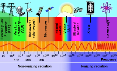
Radio frequencies are ranging from a few hertz, wavelengths of several thousands of km from peak-to-peak for brain waves, subsonic and oscillating at less than one cycle per second, to several thousands of gigahertz, wavelengths of a few mm from peak-to-peak for microwaves. Above we enter in the world of light (IR, visible, UV, X-ray and gamma). This spectrum is divided in octaves, the natural way to represent frequencies. An octave represents eight diatonic degrees and 1 octave is the interval separating two sounds whose fundamental frequency doubled : we have for example 1 octave between the standard pitch at 440 Hz (note of A or "la" in French) and a sound of 880 Hz. Humans can heard sounds (vibrations) between ~20 Hz and ~20 kHz, a range of 10 octaves (or 3 decades). Their wavelengths is ranging between 15000 km and 15 km. The electromagnetic spectrum is also arbitrary divided into "bands", among them next ones are the most important in the context of radio propagation : To download : The electromagnetic spectrum from 31.2 mHz to 6.52 EHz A poster in PDF format designed by Anthony Tekatch (722 KB) Online converter Frequency and Wavelength, Translators café
Each band extends over 3 octaves or so, the energy level increasing of about 10 times between the beginning and the end of the band. Natural radiation becomes a health hazard only from the UV light and above frequencies, even though, because all depends on the duration of exposure to the radiation, the distance to the source, and its intensity. Refer to the page dealing with EM radiations and health hazard, and well as to my pages dealing with radioactivity (in French) for more detail. ELF are only used by some submarines and to carry AC over power lines. Otherwhise, its main use is of course to carry the sound of low and mid frequencies as well infrasonic vibrations (animals). VLF are also the carrier of sound up to about 20 kHz. This band is also used for long distance communications (few thousands km) and experimentation by scientists and the Navy. LF are mainly used for regional broadcasting purposes while MF are used for worldwide broadcasting. HF are of our concern, these are formely frequencies ranging from 1.8 to 30 MHz (160-10 m bands). Know as "shortwaves", these bands are very appreciated by all radio services and operators as they allow long distance communications, broadcasting and trans-horizon radar operations.
VHF and UHF begin at 30 MHz (10 m) to end well above 1 GHz and are mainly used for radio and TV broadcasting as well as mobile communications over short distances (a few hundreds km) and more recently by cell phones. Above these frequencies we find centimetric and millimetric waves, the famous microwaves. We know them essentially through home devices like microwave ovens (Short or S-band), wireless LAN (compromise or C-band), and some satellite and radar transmissions (Kurtz or K-bands). Then close your ears and open your eyes, you enter in the near infrared and visible parts of the spectrum ! Over it, wear your anti UV-glasses to protect you against ultraviolet radiations. At last take your lead protection, we enter the world of X and g rays. As we see, most services work in the lower bands of the electromagnetic spectrum, the only one frequencies able to transport information on long distances with a very simple technology and low energy. Each band requests special receivers and aerials according to the frequency used and the type of waves (ground, space, ionospheric, etc). However these waves are affected by the medium in which they propagate, its electronic density and its dielectric constant. Alterations of radio waves If waves travel in straight line and at the velocity of light in free space, on Earth, the ground, the air and the ionosphere affect wave propagation; radio waves do no more travel from one point to another in straight line and their signals are often altered. The fading is probably the alteration that you all know if you have listened to shortwaves or old records from World War II. Radio waves are mainly subject to four effects : - Attenuation : Like the light, the intensity of the field decreases in following the inverse-distance law : when the distance double, the signal becomes half less strong. This is true in free space but on earth this attenuation is much stronger due to obstacles placed between emitter and receiver and to the fact that travelling around the earth radio waves lost their energy as they forced to bend to follow the earth curvature. A second effect is related to ground properties. A poor ground (low conductivy and dielectric constant) affects also performances of vertically polarized antennas due to the Pseudo-Brewster Angle (PBA), a situation similar to the one we experiment when the sun is low and its light reflects from the water's surface as glare, obscuring the underwater view. The reflection coefficient can exceed 90 % at 15° of elevation (21 MHz). Horizontally polarized antennas are differently affected and show an attenuation factor that never exceed 42 % (21 MHz). At last, RF currents emitted by an antenna can more or less penetrate the ground at some frequencies. For example in fresh water (lakes), RF currents penetrate up to 50m depth (156 ft), near independent of the frequency below 30 MHz. In seawater on the contrary, the depth is ranging between 18 and 5 cm only (7-2") between 1.8-30 MHz. On pastoral areas (medium hills, forestation, etc) the depth is ranging between 50 and 30 cm (20-12") over the same spectrum. - Reflection : this phenomenon, very similar to its optical counterpart, appears when a wave enters in contact with a surface more or less thick or dense. Long wavelengths, from 80 meters long and above don't practically "see" small obstacles like cars, trees or buildings. Indeed these objects are proportionally too small in regards with the wave and can't reflect its energy. The long waves pass thus across these materials without be reflected. Due to its large surface, long waves are however reflected by the ground but can penetrate it up to some meters depth. V/UHF waves (2m and 70 cm long) are on the contrary very sensitive to small obstacles. Depending of their thickness metal objects can be used as reflectors. A second type of reflection is induced by the change of dielectric constant of the medium in wich waves travel. Like a semi-transparent glass, depending the incident angle, some waves will be totaly reflected back while others coming from a lower incidence will enter the new medium without be subject to any reflection. - Refraction : this is the main reason of the bending of waves that occurs when they pass through a medium (air or ionosphere) having a different dielectric constant from the medium they have just left. These differences produce variation in the velocity of waves that tend to go further or dropping sooner that expected. Due to this effect waves change of direction like the sun light is refracted near the horizon, displacing its apparent position. In the air as the boudary between two areas of differing dielectric constant changes more slowly than the refraction index of the air for example, the wave refracts and bend gradually given the appareance that the path is curved.
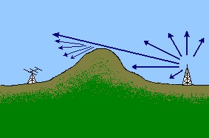
- Diffraction : Let' take for comparison its optical counterpart. At firt sight the shadow cast by a small object under strong light is very sharp. But examined closely, we can see that the shadow borders are not at all sharp. In fact due to its high frequency the light bends around the edge of the object and tends to make the borders of it shadow lighter. That means that some light reaches well some places that we considered as plunged into darkness. The same effect applies to radio waves. A spot located out of sight from a transmitter, say behind a hill, can receive weakly its emissions because its signals are bending gradually by diffraction and can reach the remote receiver. This effect has practically no influence in HF because waves arrive usually to the receiver by many other means such as refraction or reflection in the upper atmosphere, including sometimes ground waves if the transmitter is not too far (say 150-200 km away). Note that if you live near the bottom of a valley, there are some chance that you had a hill or a montain range just behind your house. If the relief is high and the landscape very close, in HF and upper bands this direction will be simply blocked up for Yagi's. You are "condemned" in using a high-end vertical antenna that, thanks to its omnidirectional pattern and vertical polarization will help you in jumping over this obstacle. Interfering together, all these effects tend to replace the fine straight path followed by radio waves by a sort of large undulating and curved beam that widen as the distance and frequency increase and scatters in the atmosphere just like the light. This is even all benefit for radio amateurs that can receive by these means signals under conditions as unexpected as behind hills or thanks to atmospheric ducting or auroral events, other modes of traffic that we will review on the next pages. Propagation of waves The success or the failure of a radio transmission depends on the way that radio signals travel around the earth. Basically there are five types of propagation : - Ground waves : also called evanescent or surface waves, these waves propagate along the earth surface, close to the ground, and never reach the ionosphere. Typically signals carried by ground waves can be heard up to a distance of 160 km or more during the daytime. They are however subject to a high attenuation throughout HF bands to reach distances less than 15 km at 30 MHz.. Therefore these surface waves are mainly used at low frequencies below 1.8 MHz (MW, LW and VLF) by geophysicists and the maritime services (submarines). - Tropospheric waves : below 10 km or so of the atmosphere, where weather patterns and temperature inversions form, VHF can be refracted permitting short distances contact (a few thousands km). This activity will be shortly discussed as well as the atmospheric ducting, also induced by temperature inversions. - Space waves : these waves travel directly from an antenna to another without reflection on the ground. This phenomenon occurs when both antennas are within line of sight of each another. The distance to the horizon is given by the next formula : D (km) = 4.124√H, where H is the antenna heigth in meters above ground. This distance is longer that the line of sight because most space waves bend near the ground and follow practically a curved path. In the field, we must also add the effects of the atmospheric refraction and diffraction near the earth surface that extend this distance of about 20 % in the lowest bands. Conversely, on UHF and upper bands, diffraction is very small and signals tend to drop off quite rapidely at a shorter distance. Antennas must display a very low angle of emission in order that all the power is radiated in direction of the horizon instead of escaping in the sky. A high gain and horizontally polarized antenna is thus highly recommended.
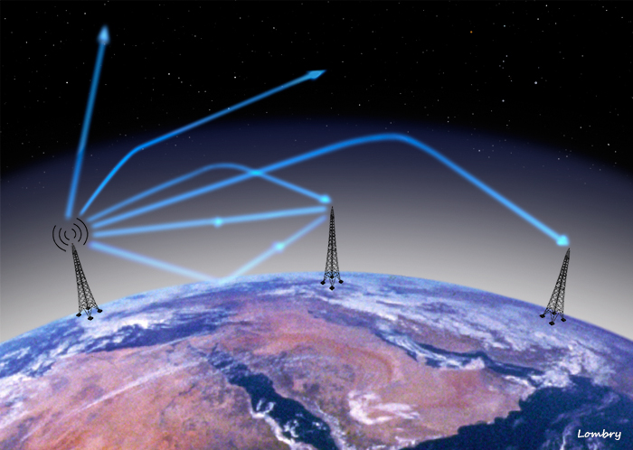
- Sky waves : They essentially concern frequencies below 30 MHz (longer than 10 meters) and V/UHF in a less extent that are able to escape into free space (that begins over 800 km aloft). Called sky waves these waves are however stopped in their travel by the ionospheric layers and, under low incidence angles, they are reflected to the ground. These waves are then called ionospheric waves. They are very influenced by the presence of electrons gas and plasma in the upper atmosphere of the Earth. Under certain conditions these layers reflect or refract shortwaves, permitting amateurs to reach stations located on the other side of the Earth in a succession of jumps between the ground and the ionosphere, called multihops. We will develop this subject in depth on the next page as they are the most used by radio amateurs. In another article we will deal about perturbations affecting sky waves propagation in the ionosphere. - Free space waves : they are the most common but the less used ! We encounter them working in VHF or UHF where, due to their very high frequency, at incidence angles higher that the critical angle, shortwaves escape into space instead of be reflected by ionospheric layers. This way of propagation is sometimes welcome to work with an ham satellite in polar orbit or with ISS which signals pass through ionospheric layers. As we told, the propagation that is our concern - amateurs and listeners - are sky waves and mainly the ones propagating in HF bands. However, to be complete we will do a short excursion in the higher bands as well Next chapter
|
|||||||||||||||||||||||||||||||||||||||||||||||||||||||||||||||||||||||||||||||||||||||||||||||||||||||||||||||||||||||||||||||||||||||||||||||

