Contrast factor of the F-P etalon and blocking filter assembly
3) Daystar filter modelling and additional results
4) Air-spaced F-P etalon theoritical performances and comparison with mica-spaced etalons
5) Analysis of the PST modification (air-spaced F-P etalon) and comparison between collimated and telecentric mounts
6) Contrast factor of the F-P etalon and blocking filter assembly
7) Contrast factor of the F-P etalon : test of various stacking schemes
8) Fabry-Perot math and bibliography
Test 1 : Daystar PE 0.6A versus Daystar PE 0.6 A stacked with Omega 4.5 A filter
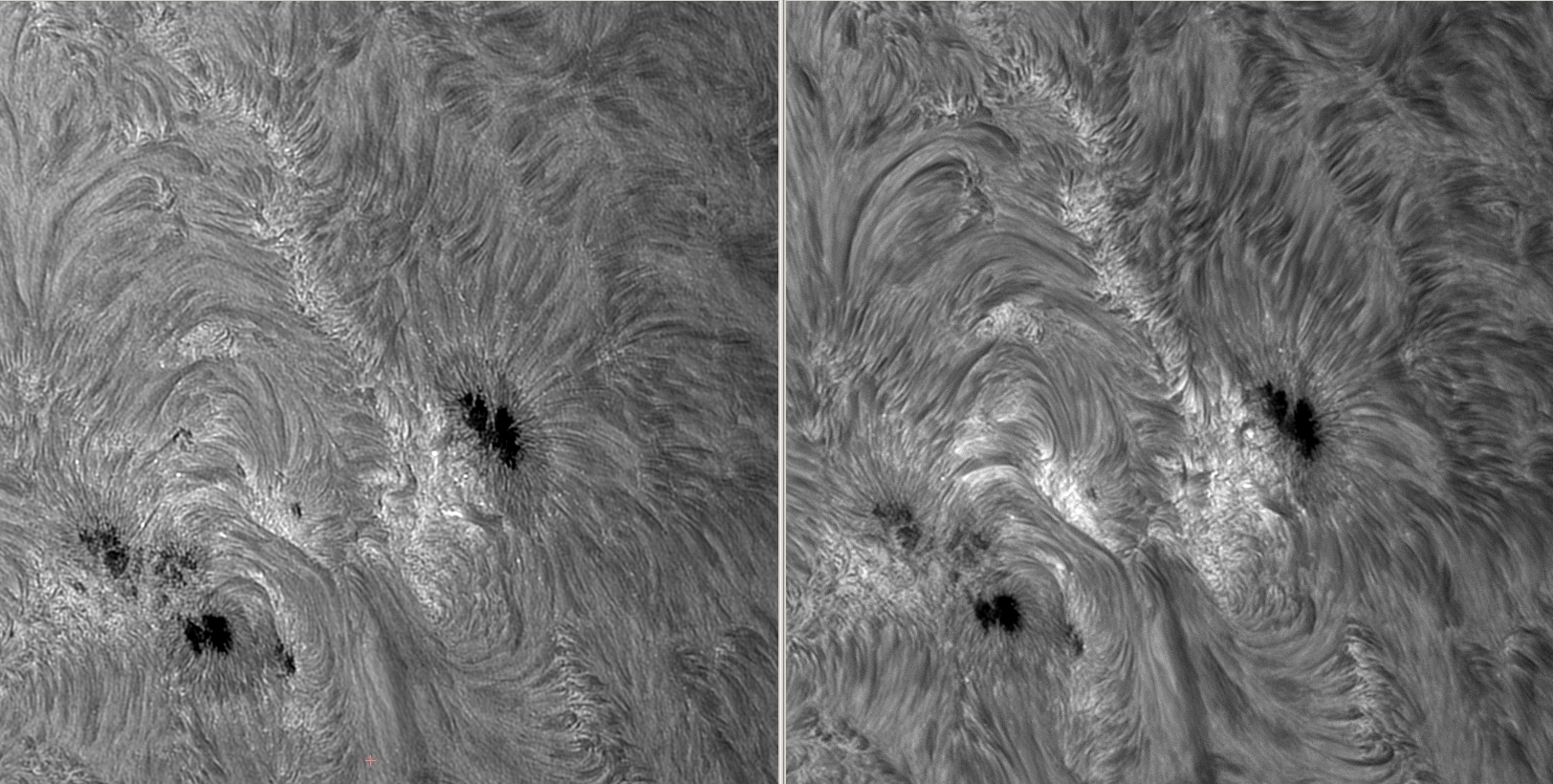
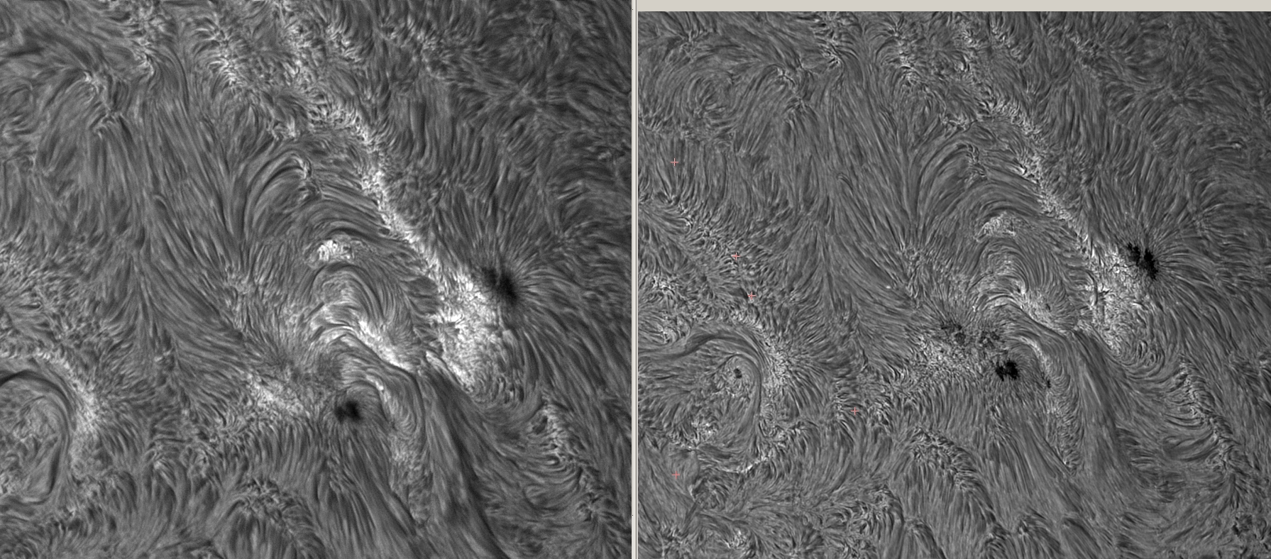
Test 2 : PE 0.6A, PE 0.6A + TO 0.9A, Ion 0.3A , PE 0.6A + Ion 0.3A
Test 3 : PE 0.6A, PE 0.6A + TO 0.9A etalon, Ion 0.3A
Test 4 : 0.6A to 0.3 A mica-spaced etalon stacked with top quality 1.5A hard-coated filter
Test 5 : 0.6 A mica-spaced etalon stacked with 0.5A SMN35 fused silica etalon
A lot of care was taken to carry out this test in order to reach a reliable conclusion :
- squareness of the Daystar filter to the optical axis checked by auto-collimation and tuned to better than 0.1°,
- Baader TZ4 telecentric system given F/28 ratio
- similar seeing conditions (average 1.3 arcsec measured with Airy Lab Solar Seeing Monitor),
- focussing accuracy is the same for all images (measured with a gauge),
- 200 Go of images were captured, the result presented here is not accidental and is consistent all over the 200 Go data set.
- images dark and flat corrected,
- images with / without Omega filter have exactly the same processing (unsharp mask + linear visualization).
The only differences between the images are :
- exposure time : 3 ms for images with the "PE 0.6 A only", and 9 ms for " PE 0.6 A stacked with the Omega 4.5 A",
- visualization treshold.
Here are some details on the Ha Omega filter taken from the tranmission profile provided by Omega :
- max transmission 38%,
- 4.5 A FWHM (still ... Omega says this value is overestimated by their spectrometer).
- mounted in a tilt mechanism to tune the band on Ha.
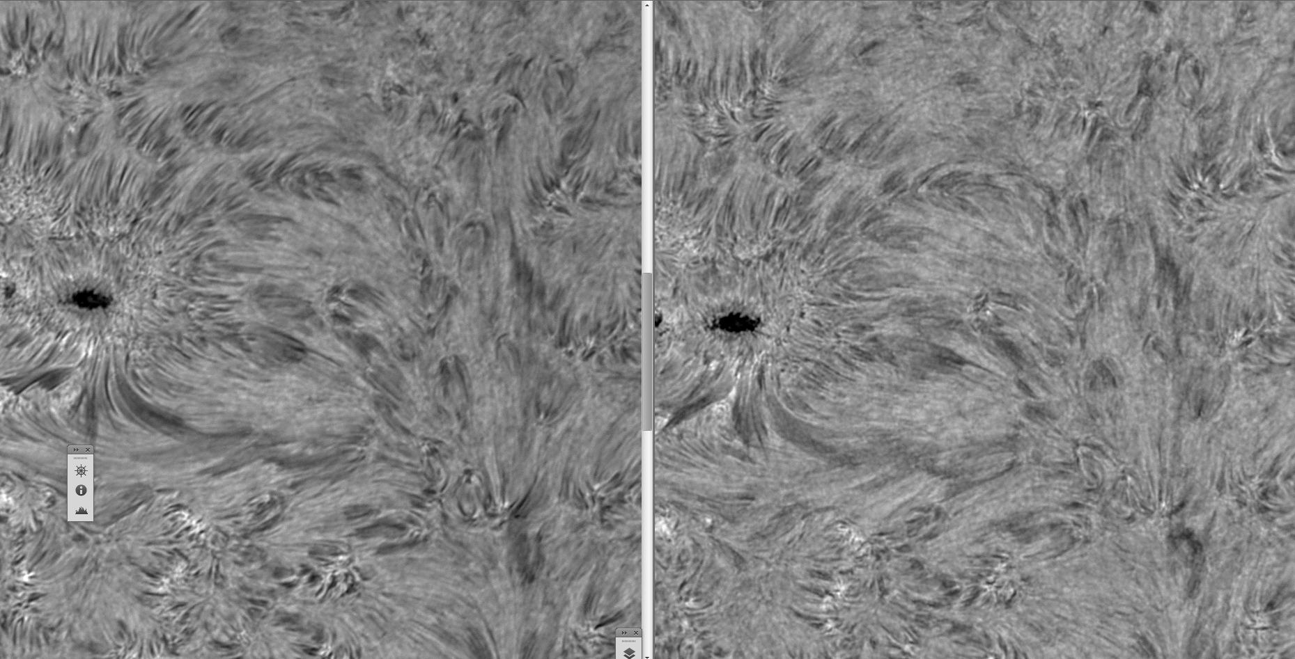
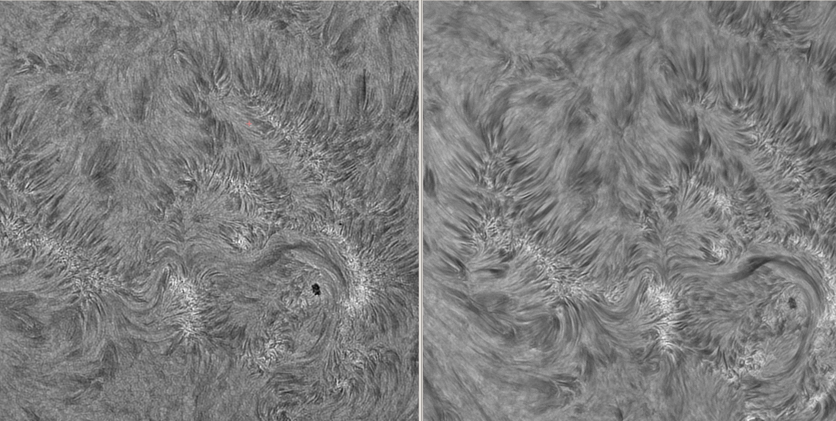
Now, here is an example of side by side comparison images. Other images taken on that same day give similar results. So the results is not an artifact due to the seeing, umperfect focus or whatever.
"Daystar PE 0.6A stacked with Omega 4.5 A" on left side, "Daystar PE 0.6A alone" on right side :
What can we see on these images ?
As explained in the previous "theoritical" analysis, the solar granulation from the photosphere is clearly seen on the "Daystar alone" image. The image looks "grainy". This is not a noise issue, but the solar granulation seen through the Ha. The filaments and the spicules bushes are less dense. The "Daystar alone" image captures a lot of unwanted photospheric light which reduces the visibility of Ha features.
The "Daystar stacked with the Omega 4.5 A" is much more selective to Ha. Still some small amount of granulation is visible, but to a much lower extend than in the "Daystar alone" image.
The links to the full-size images are here. Additional information on data acquisition are given on the image ::
Daystar stacked with Omega 4.5 A
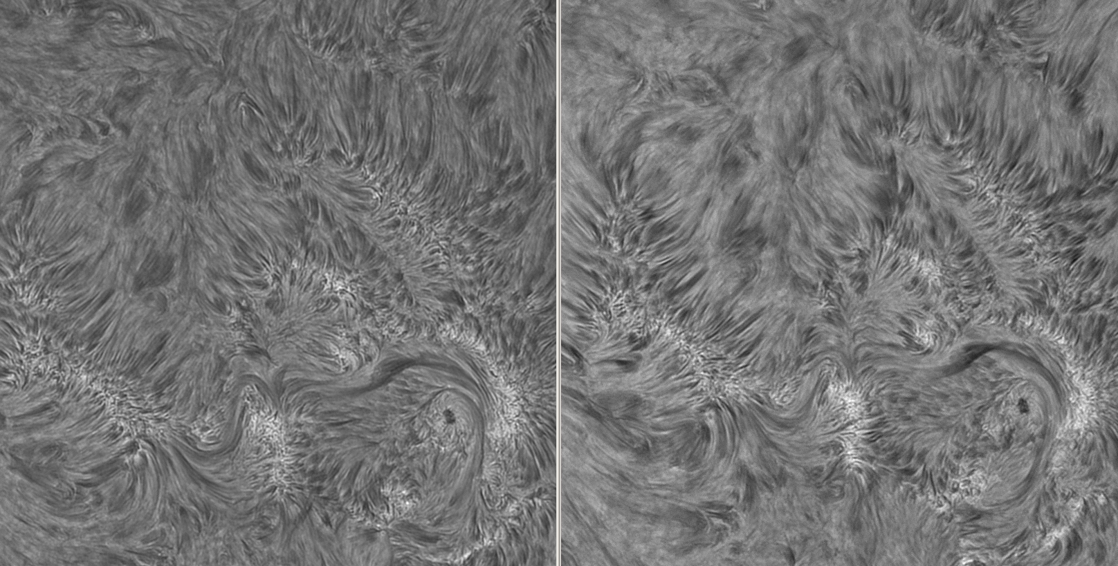
Comparison of CWL and FWHM uniformity :
The difference uniformity is best seen when the size of the images is reduced (Daystar + Omega filter on left side) :
When observed carefully, the CWL and / or the FWHM is not completly uniform all over the image taken with "Daystar stacked with the Omega 4.5 A". This is mainly true for the upper right coner. The size of the CMOSIS 4000 sensor is 10 mm x 10 mm, to be compared with the 25 mm diameter of the Omega filter.
Thousand Oaks 0.9A filter mounted in tilt support.
Acquisition data :
| Exposure | Gain | Gamma | |
|---|---|---|---|
| PE 0.6 A |
300 frames x 8 ms
|
3 700
|
1.1
|
| PE 0.6A + TO0.9A |
300 frames x 20 ms
|
21 000
|
1.1
|
Processing :
Same processing and display gamma = 1 for both images.
Comments :
Transmission of the TO 0.9A is far from uniform over the field of view.
The TO 0.9A filter increases exposure times by about 15 times.
In the PE 0.6A image, the photospheric granulation is visible through the chromosphere layer.
Acquisition data :
| Exposure | Gain | Gamma | |
|---|---|---|---|
| Ion 0.3A |
300 frames x 8 ms
|
21 000
|
1.1
|
| PE 0.6A + TO0.9A |
300 frames x 20 ms
|
21 000
|
1.1
|
Processing : ages.
Comments :
Ion 0.3 A is about 3 times more luminous than the PE 0.6A + TO 0.9A configuration, for about the same blocking of photopheric light. Shorter exposure times results in better resolution and higher S/N.
The PE 0.6A + TO 0.9A configuration looks a little bit more selective than the Ion 0.3A. The Center Wave Lenght is probably not exactly the same in both images (tuned by tilt mechanism for the TO 0.9A and potentiometer for the Ion 0.3A).

Acquisition data :
| Binning | Exposure | Gain | Gamma | |
|---|---|---|---|---|
| Ion 0.3A |
1 x 1
|
300 frames x 8 ms
|
21 000
|
1.1
|
| PE 0.6A + Ion 0.3A |
2 x 2
|
300 frames x 20 ms
|
21 000
|
1.1
|
PE 0.6A and Ion 0.3A where aligned in rotation in order to maximize transmission (only 20% difference between best and worse settings). The tilt of both filters were tuned so the filters were square to the optical axis.
Processing :
Drizzle 150% for PE 0.6A + Ion 0.3A stack.
Resize 0.66% for the Ion 0.3 A image.
Otherwise same processing and display gamma = 1 for both images.
Comments :
PE 0.6 + Ion 0.3A stack is about 10 times less luminous than Ion 0.3A. High resolution imaging is unfortunately no longer possible.
Selectivilty of PE 0.3 A + 0.6A stack is simply amazing, The chromsphere image is no more polluted by the photopheric light. The double limb effect is no longer visible. Some of the sunpots are no longer visible, beeing covered by the chromospheric fibriles.
Double limb effect no longer visible with the Ion 0.3 + PE 0.6 A stack :
Direct output images from Autostakkert 2, no processing. Linear visualisation of the whole dynamic of each image.
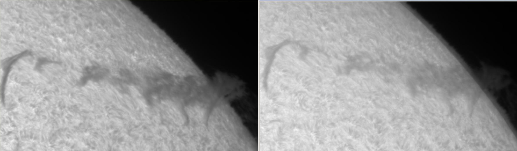
It comes at no surprise that stacking a mica-spaced etalon increases the contrast of the image by reducing the photospheric light. The double limb effect disappears visually with a 0.7 A + 0.6A stack.
The problem is to find out a good (i.e high peak transmission, uniform, durable) "large band" Ha etalon to stack on a mica-spaced etalon. There are two main options :
1) A dielectric filter (refractive index > 1) mounted in a tilt system would be an advantage because of a small size and reduced FWHM broading in telecentric beam.
- 1 to 1.5A FWHM would be nice matches to 0.3 A to 0.8 A mica-spaced etalons.
- The Ha Omega filter tested here is not suitable because of its very poor optical quality.
- The TO 0.9A would be a nice fit if it had a much better peak transmission.
2) An air-spaced etalon (eg. PST etalon, Lunt LS50, etc) stacked on the mica-spaced etalon would have a good peak transmission. Because of the telecentric beam, a 0.7 A FWHM air-spaced etalon would have an effective 1.1 A FWHM at F/D 30.
We are still left to find out a 1.5 A FWHM Ha filter with a good peak transmisison, optical quality, uniformity and durability ...