- Theoretical Elements
- SHG with a 115/900
- SHG with 90/1300 refractor (p.1
 )
) - SHG with 90/1300 refractor (p.2 )
- Newton 192/950
- Dobson 80/400 'Babydob'
- Ultra-simple solar spectrum
- Misc. electronic layouts
- Misc. optical layouts
- Untransversaliumisator software
- Processing videos software
- "PUSH TO" DIY system
- Radio control RA, Dec & focus
- Focuser 3D pour Vixen 150/750
- Year :
- Synoptic maps :
- Videos
- Maunder's Diagram
- Cycle 23 in images
- Venus Transit 2004
| Spectroheliograph with a 115/900mm reflector
| ||||
|
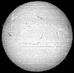
Introduction It is about amateur's realization which, at first (1990), consisted in making a prototype to test the possibility to build a SHG. The presence of a microcomputer at home as well as a linear CCD, and especially the recovery of a grating, allowed this starting up. Thus the budget should be minimum and the "D.I.Y. system" largely used. The constraints were severe because the first version of the SHG should be in "piggy-back" on a classic 115/900 telescope supported by the most classic and frail equatorial mounting on a wooden tripod. Useless to specify that the weight and the dimensions of the spectro should be minimum too ! Where starting ? The purpose is to make the smallest possible spectroheliograph giving at the same tme a sufficient spectral resolution to make appear chromospheric structures in Ha or K lines on the sun disc (about 0,05 nm), and a sufficient spatial resolution so that these same structures are clear and detailed. It is in fact the size and the number of photoelements of the CCD which will guide, or determine, the continuation of the realization Dispersion and spectral resolution If 1 pixel of the CCD is about 10µm wide (perpendicular direction to the axis of the bar), it is necessary that the dispersion of the spectrum is such as this 10µm intercepts a spectral band of 0,05 nm (We will say that the dispersion is 5 nm / mm). This dispersion is a function of 3 elements: The number of lines by mm of the grating, the order of the grating, and the focal length of the camera lens (the one that forms the image of the spectrum). Dispersion increases if these parameters increase. Dispersion is not all, it is also necessary to take
account spectral resolution. Nothing serves for having a strong
dispersion if the resolution is not good. The problem is the same
one as a telescope. Let us suppose an objective of 1,2 m focal
length and 100 mm in diameter, good quality. This objective is
able to give at focus plane an image of the Moon of 10mm in diameter.
If we reduce to 20 mm the aperture of the objective by means of
a diaphragm, the image of the Moon measures always 10 mm in diameter
but the resolution of details is 5 times less good. Matériel et réalisation The elements which I had were the following ones: a linear
CCD Thomson TH7803 made up of 1728 photodiodes of 10x13µm in the step of 10 µm,
a plane reflection grating 1180 grooves per mm and 62 mm aside. Spatial resolution :
with : Obtaining of a 17 mm solar image requires an objective of almost 2 m focal length. 1 pixel (10 µm) represents then a little more than 1 arc-second. An objective of 12 cm in diameter can - always in theory - allow this resolution but let us not forget that we observe the Sun and that the turbulence is generally limiting. One will thus gain nothing in resolution by using a larger objective.
After this first experiment and an unproductive period of a few years, I consider again the construction of a SHG because certain favorable circumstances were gathered. I built an equatorial mounting motorized in right ascension and in declination for my 115/900 telescope. Intended originally for the photography of the deep sky with a 500 mm telephoto lens in parallel with 115/900, the stability, robustness and convenience are without comparison with the first mounting. The recovery of a new grating - although far from the new state - blazed 500 nm and 1440 grooves per mm, the diversion of an other linear CCD from a hand-scanner and the purchase of a microcomputer revived my interest for SHG. Here is the description of this instrument that is however only an example and each can modify and improve it. Optical components :
Particular mechanical elements :
The electronic elements :
The microcomputing :
The optical layout As a drawing is better that 10000 words, here is the plan of the arrangement of the optical components constituting the SHG. Telescope is in the bottom. 
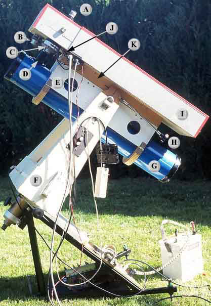
Global aspect of the spectroheliograph
|
||||
 |